Manual: 152-082010 301-305-306_303-307 Series Page 21 of 35
1.75"(44.5 mm) diameter. The base and endcap seal is an O-ring gland configuration, which uses Viton
as a standard sealing material. The HFM-305/306 is made from a larger 3.0” by 3.0” (76.2 mm by 76.2
mm) cross section of 316 stainless steel and has a length of 5.3” (134.6 mm) while the 307 has a length
of 8” (203.2 mm). The 305/307 however has a larger 2.67” (67.8 mm) internal flow channel and knife
edge metal to metal seals on the end caps. Between the base and sensor module on the 300 Series is a
knife edge metal to metal seal. Gaskets made of nickel 200 are swaged between mating face seals
machined into the stainless steel parts. All seals are tested at the factory and have leak rates of less
than 1x10
-9
std. cc/s.
The HFM-306 base is much larger. The base/end cap seal is an O-ring gland configuration, which uses
Viton as a standard sealing material.
3.5. Shunt description
The flow rate of interest determines the size of the shunt required. As previously indicated, the
301/305 series can be configured from 25 to 2500 slm (303/307 controller from 25-2500 slm) using
various base, shunt and transducer combinations. The shunts employ a patented method of flow
division, which results in a more linear flow meter/controller; further calibration is more stable when
changing between measured gases.
The shunts are comprised of a 316 stainless steel cylindrical shell concentrically located in the base that
forms an annular flow channel of precise dimension. This flow channel creates laminar flow by the
inboard sensor taps. The cylindrical shell encases a corrugated matrix of flow channels which serve as a
shunt. The size and number of these channels is consistent with the sensor ∆P and flow range.
3.6. Shunt Theory
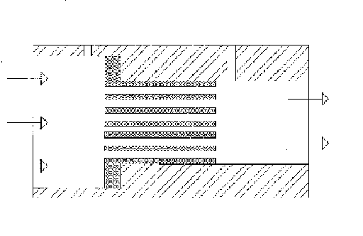
A flow divider for a thermal mass flow transducer usually consists of an inlet plenum, a flow restriction,
shunt and an outlet plenum. (See Figure 3-1). Since stability of the flow multiplier is desired to ensure a
stable instrument, there must be some matching between the linear volumetric flow versus pressure
drop of the sensor and the shape of the volumetric flow versus pressure drop of the shunt. Most
instruments employ Poiseuille’s law and use some sort of multi-passage device that creates laminar flow
between the upstream sensor inlet and the downstream outlet. This makes the volumetric flow versus
pressure drop curve primarily linear, but there are other effects which introduce higher order terms.
Most flow transducers are designed such that the outlet plenum has a smaller diameter than the inlet
plenum. This eases the insertion and containment of the shunt between the sensor inlet point and the
sensor outlet point. However there will be a pressure drop between the sensor inlet and outlet points
created by the change in flow passage diameter. Since the drop is a square function of the flow velocity
the differential pressure will be non-linear with respect to flow rate. Note also that the pressure drop is
a function of density.
The density will vary as a function of system
pressure and it will also vary when the gas
composition changes. This will cause the
magnitude of the pressure drop due to the area
change to be a function of system pressure and
gas composition.
Most of the shunts used contain or can be
approximated by many short capillary tubes in
parallel. We know that the equation for the
pressure drop across a capillary tube contains
terms that are proportional to the square of the
volumetric flow rate. These terms come from
the pressure drops associated with the sudden
c
ompression at the entrance and the sudden expansion at the exit of the capillary tube. The end effect
terms are a function of density which will cause the quadratic term to vary with system pressure and gas
composition. The absence of viscosity in the second term will cause a change in the relative magnitudes
of the two terms whenever the viscosity of the flowing gas changes.
Figure 3-1