


Manual: 152-082010 301-305-306_303-307 Series Page 20 of 35
(
)
PP mCT T
ud pheaterambient
−= −
•
2
conducted from the upstream and downstream coils to the foam insulation surrounding them is assumed
to be equal, based on the symmetry of the sensor construction.
Since the sensor tube inlet and outlet are linked by an aluminum ambient bar, the high thermal
conductivity of the bar provides a ‘thermal short’, constraining the ends of the sensor tube to be at
equal surface temperature. Moreover, the tube ends and the aluminum ambient bar have intimate
thermal communication with the main flow passageway prescribed by the main stainless steel flow meter
body. This further constrains each end of the sensor tube to be equal to the ambient gas temperature.
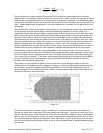
Further, since the length of each heater section is nearly 21 times greater than the inside tube diameter,
the mean gas temperature at the tubes axial midpoint is approximately equal to the tube surface
temperature at that point. Recall that the outside of the sensor tube is well insulated from the
surroundings; therefore the tube surface temperature at the axial midpoint is very close to the operating
temperature of the heater coils. The mean temperature of the gas stream is then approximately the
same as the heater temperature. Assuming the mean gas temperature is equal to the heater
temperature, it can be shown that the differential power is:
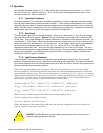
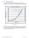
The value of the constant pressure specific heat of a gas is virtually constant over small changes in
temperature. By maintaining both heaters at the same, constant temperature difference above the
ambient gas stream temperature, the difference in heater power is a function only of the mass flow
rate. Fluctuations in ambient gas temperature which cause errors in conventional mass flow sensors are
avoided; The resistance of the ambient sensing coil changes proportionally with the ambient
temperature fluctuations, causing the closed loop control to vary the bridge voltage such that the heater
resistance changes proportionally to the ambient temperature fluctuation.
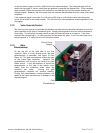
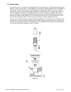
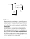
The power supplied to each of the 2 heater coils is easily obtained by measuring the voltage across the
heater, shown as V2 on Figure 3.2, and the voltage across the fixed resistor R1. Since R1 is in series with
the heater RH they have the same current flowing through them. The electrical power supplied to a
given heater is then calculated:
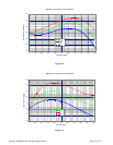
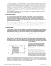
With a constant differential temperature applied to each heater coil and no mass flow through the
sensor the difference in heater power will be zero. As the mass flow rate through the sensor tube is
increased, heat is transferred from the upstream heater to the gas stream. This heat loss from the
heater to the gas stream will force the upstream bridge control loop to apply more power to the
upstream heater so that the 48
o
C constant differential temperature is maintained.
The gas stream will increase in temperature due to the heat it gains from the upstream heater. This
elevated gas stream temperature causes the heat transfer at the downstream heater to gain heat from
the gas stream. The heat gained from the gas stream forces the downstream bridge control loop to apply
less power to the downstream heater coil in order to maintain a constant differential temperature of 48
o
C.
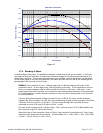
The power difference at the RTD’s is a function of the mass flow rate and the specific heat of the gas.
Since the heat capacity of many gases is relatively constant over wide ranges of temperature and
pressure, the flow meter may be calibrated directly in mass units for those gases. Changes in gas
composition require application of a multiplication factor to the nitrogen calibration to account for the
difference in heat capacity.
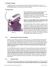
3.4. Base
The 316 stainless steel base has a 2.0" by 2.0” (50.8 mm by 50.8 mm) cross-section and is 5.77"(146.6
mm) long on the HFC-303 and 4.32” (109.7 mm) long on the HFM-301. Lower flow (< 300 SLM) 301's are
0.2" shorter and lower flow 303's are 0.4" shorter. The base has an internal flow channel that is
(
)
P
VVV
R
=
−
122
1