


Manual: 152-082010 301-305-306_303-307 Series Page 19 of 35
3. Theory and Function
3.1. Overall Functional Description
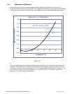
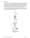
The 300 Series flow meters consist of a sensor, base, shunt, control valve (303/307) and electronic
circuitry. The sensor is configured to measure gas flow rate from 25-10000 slm, depending on the
customer’s desired overall flow rate. The shunt divides the overall gas flow such that the flow through
the sensor is a precise percentage of the flow through the shunt. The flow through both the sensor and
shunt is laminar. The control valve adjusts the flow so that the sensors measurement matches the set-
point input. The circuit board amplifies the sensor output from the two RTD’s (Resistive Temperature
Detectors) and provides an analog output of either 0 - 5 VDC or 4 - 20 mA.
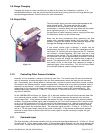
3.2. Sensor Description
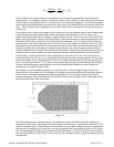
The sensor consists of two coils of resistance wire with a high temperature coefficient of resistance
(3500 ppm/
o
C) wound around a stainless steel tube with internal diameter of 0.014”(0.36mm),
0.017”(0.43mm) or 0.026”(0.66mm) and 3.00” (7.62) cm length. These two identical resistance wire
coils are used to heat the gas stream and are symmetrically located upstream and downstream on the
sensor tube. Insulation surrounds the sensor tube and heater coils with no voids around the tube to
prevent any convection losses. The ends of this sensor tube pass through an aluminum block and into the
stainless steel sensor base. This aluminum block thermally shorts the ends of the sensor tube and
maintains them at ambient temperature.
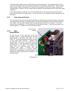
There are two coils of resistance wire that are wound around the aluminum block. The coils are identical
to each other and are symmetrically spaced on the aluminum ambient block. These coils are wound
from the same spool of wire that is used for the sensor heater coils so they have the same resistivity and
the same temperature coefficient of resistance as the sensor heater coils. The number of turns is
controlled to have a resistance that is 10 times larger than the resistance of the heater coils. Thermal
grease fills any voids between the ambient temperature block and the sensor tube to ensure that the
ends of the sensor tube are thermally tied to the temperature of this aluminum block.
Aluminum has a very high thermal conductivity which ensures that both ends of the sensor tube and the
two coils wound around the ambient block will all be at the same temperature. This block is in good
thermal communication with the stainless steel base to ensure that the ambient block is at the same
temperature as the main instrument block and, therefore, the same temperature as the incoming gas
stream. This allows the coils wound on the aluminum block to sense the ambient gas temperature.
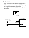
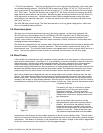
Two identical Wheatstone bridges are employed, as shown in Figure 3.2. Each bridge utilizes an ambient
temperature sensing coil and a heater coil. The heater coil and a constant value series resistor comprise
the first leg of the bridges. The second leg of each bridge contains the ambient sensing coil and two
constant value series resistors. These Wheatstone bridges keep each heater temperature at a fixed value
of ∆T = 48
o
C above the ambient sensor temperature through the application of closed loop control and
the proper selection of the constant value bridge resistors.
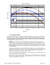
3.3. Sensor Theory
The heat transferred by convection to or from a fluid is proportional to the mass flow of that fluid. Since
the constant differential temperature sensor has 2 heater coils symmetrically spaced on the sensor tube,
it is convenient to consider the upstream and downstream heat transfer modes separately. The electrical
power supplied to either of the heater coils will be converted to heat, which can be dissipated by
radiation, conduction, or convection. The radiation term is negligible due to the low temperatures used
by the sensor, and because the sensor construction preferentially favors the conductive and convective
heat transfer modes. The thermal energy of each heater will then be dissipated by conduction down the
stainless steel sensor tube, conduction to the insulating foam, plus the convection due to the mass flow
of the sensed gas.
Because great care is taken to wind the resistive heater coils symmetrically about the midpoint of the
tube, it is assumed that the heat conducted along the sensor tube from the upstream heater will be
equal to the heat conducted through the tube from the downstream heater. Similarly, the heat