


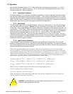
Manual: 152-082010 301-305-306_303-307 Series Page 15 of 35
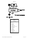
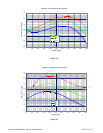
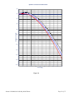
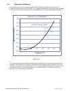
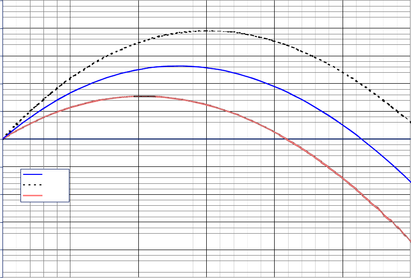
Span Error vs Pressure
-1.0%
-0.8%
-0.6%
-0.4%
-0.2%
0.0%
0.2%
0.4%
0.6%
0.8%
1.0%
0 50 100 150 200 250 300
Pressure(psig)
Span Error (% reading)
Mean error
max
min
Figure 2-7
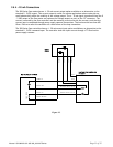
2.7.4. Blending of Gases
In the blending of two gases, it is possible to maintain a fixed ratio of one gas to another. In this case,
the output of one flow controller is used as the reference voltage for the set point potentiometer of a
second flow controller. The set point potentiometer then provides a control signal that is proportional
to the output signal of the first flow controller, and hence controls the flow rate of the second gas as a
percentage of the flow rate of the first gas.
EXAMPLE: Flow controller A has 0 - 100 slm range with a 5.00 volt output at full scale. Flow
controller B has 0 - 10 slm range with a 5.00 volt output at full scale. If flow controller A is set at
80 slm, its output voltage would be 4.00 volts (80 slm/100 slm x 5.00 volts = 4.00 volts). If the
output signal from flow controller A is connected to the command potentiometer of flow controller
B, it then becomes a variable reference voltage for flow controller B proportional to the flow rate
of flow controller A.
If the set point potentiometer of flow controller B is set at 50% of full scale, and the reference
voltage from flow controller A is 4.00, then the command signal going to flow controller B would be
2.00 volts (4.00 volts x 50.0% = 2.00 volts). The flow of gas through flow controller B is then
controlled at 4 slm (2.00 volts/5.00 volts x 10 slm = 4 slm).
The ratio of the two gases is 20:1 (80 slm/4slm). The % mixture of gas A is 95.2 (80slm/84slm and
the % mixture of gas B is 4.8% (4 slm/84 slm).
Should the flow of flow controller A drop to 78 slm, flow controller B would drop to 3.9 slm, hence
maintaining the same ratio of the mixture. (78 slm/100slm x 5v = 3.90v x 50% = 1.95v; 1.95v/5.00v
x 10 slm = 3.9 slm; 78 slm: 3.9 slm = 20:1)