


Manual: 152-082010 301-305-306_303-307 Series Page 7 of 35
2. Operation
This section contains the necessary steps to assist in getting a new flow meter/controller into operation
as quickly and easily as possible. Please read the following thoroughly before attempting to install the
instrument.
2.1. Receiving Inspection
Carefully unpack the Hastings 300 Series instrument and any accessories that have also been ordered.
Inspect for any obvious signs of damage to the shipment. Immediately advise the carrier who delivered
the shipment if any damage is suspected. Check each component shipped with the packing list. Insure
that all parts are present (i.e., flow meter, power supply, cables, etc.). Optional equipment or
accessories will be listed separately on the packing list. There may also be one or more OPT-options on
the packing list. These normally refer to special ranges or special gas calibrations. They may also refer
to special helium leak tests, or high pressure tests. In most cases, these are not separate parts, but
special options or modifications built into the flow meter.
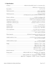
2.2. Power Requirements
The HFM-301/305/306 requires ±15 VDC @ 55 mA. The HFC-303/307 requires ±15VDC @ 150 mA for
proper operation. The supply voltage should be sufficiently regulated to no more than 50 mV ripple.
The supply voltage can vary from 14.0 to 16.0 VDC. Surge suppressors are recommended to prevent
power spikes reaching the instrument. The Hastings power supply described in Section Error! Reference
source not found. satisfies these power requirements.
2.3. Output Signal
The standard output of the flow meter is a 0 - 5 VDC signal proportional to the flow rate. In the Hastings
power supply the output is routed to the display and is also available at the terminals on the rear panel.
If a Hastings supply is not used, the output is available on pin 6 of the “D” connector. It is recommended
that the load resistance be no less that 2 kΩ. If the optional 4 - 20 mA output is used, the load
impedance must be less than 600 Ω.
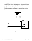
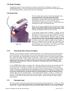
2.4. Mechanical Connections
The flow meter may be mounted in any position as long as the direction of gas flow through the
instrument follows the arrow marked on the bottom of the flow meter case label. The preferred
orientation is with the inlet and outlet fittings in a horizontal plane. If operating with a dense gas (e.g.
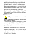
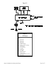
Quick Start
1. Insure flow circuit mechanical connections are leak free.
2. Insure electrical connections are correct (See label).
3. Power up. (Allow 30 minutes to 1 hour warm-up for best accuracy.)
4. Note the flow signal decays toward zero.
5. Run ~20% flow (~ 1 VDC) through instrument for 5 minutes.
6. Insure zero flow; wait 2 minutes, then zero the instrument.
7. Instrument is ready for operation.