


5.53
BODY / STEERING / SUSPENSION
5
9923142 - 2011 RANGER RZR / RZR S / RZR 4 Service Manual
© Copyright 2010 Polaris Sales Inc.
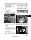
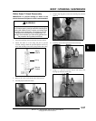
28. Install IFP bleed screw and tighten using the 1/8” hex tool.
Remove the IFP depth setting tool. Pour the residual oil out
of the reservoir tube into a proper disposal container.
29. Install the reservoir end cap with the FOX™ air valve
facing the outside of the reservoir tube. Push down on the
reservoir end cap using even pressure, until the retaining
ring groove is exposed. Install the wire retaining ring, and
check to make sure retaining ring is seated properly.
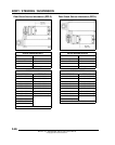
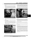
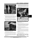
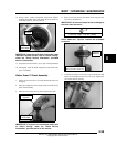
30. Push the shaft assembly completely into the body tube
(Fig. 18). It should go all the way down smoothly and
without interference. If it does not, disassemble and
reassemble per this procedure. Do not attempt to pull the
shaft assembly back out by hand.
31. If reservoir cap is not properly seated against the retaining
clip, tap it gently with a rubber mallet until it snaps into
place. Remove shock assembly from vise.
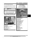
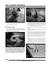
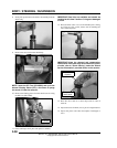
32. Securely clamp FOX™ Nitrogen Safety Needle in the vise.
Be sure to point the air valve away from your face and body.
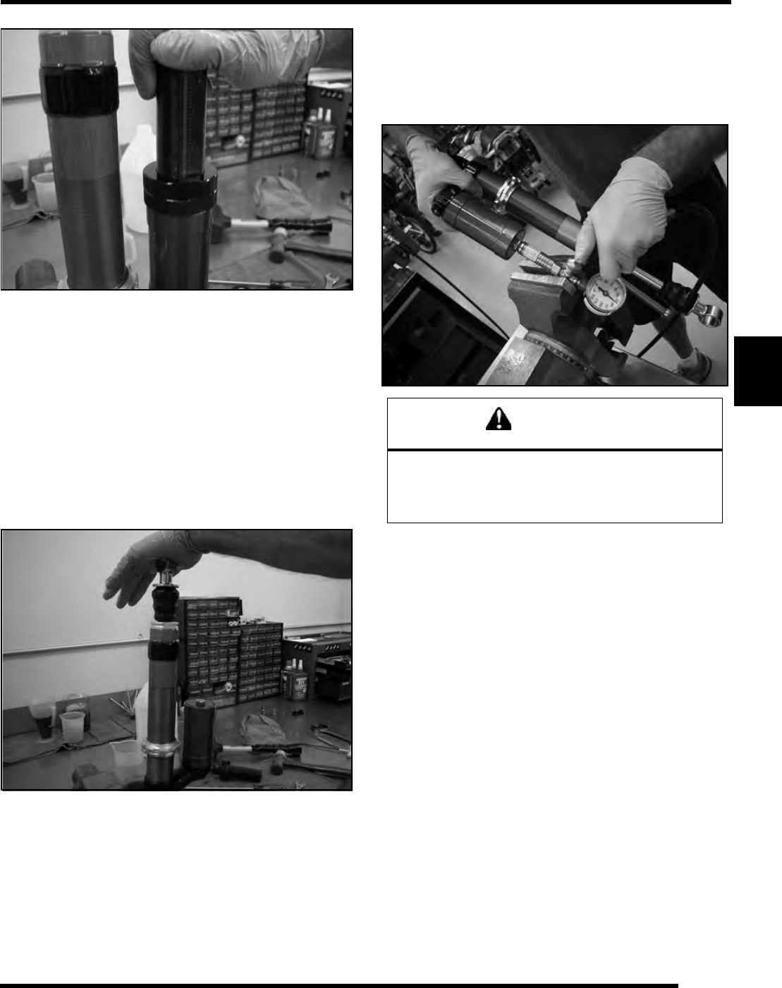
33. Insert the safety needle squarely into center of FOX™ air
valve, and pressurize the reservoir. Continue filling until
the shaft has fully extended and the reservoir pressure is at
200 psi (Fig. 19).
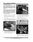
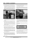
34. Continue charging with gas as you pull the reservoir away
from the FOX™ Nitrogen Safety Needle using a smooth,
straight motion. Keep the reservoir as straight as possible
to prevent the safety needle from bending. As the safety
needle is pulled free from the FOX™ air valve, a popping
sound should be heard.
35. Install the button-head screw into the FOX™ air valve,
using a 3/32” hex key.
36. Remove the shock from the vise.
37. Clean all oil residue from the shock and reservoir with
solvent, and dry with compressed air in a well ventilated
area. If compressed air is not available, dry the shock and
reservoir using clean, lint free paper towels and let sit in a
well ventilated area to allow the solvents to evaporate.
38. Reinstall the spring and the spring retainer.
39. Thread the spring preload ring down against the spring, and
set the preload to the measurement you took when you
removed the spring.
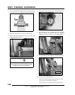
40. Using the flat blade screwdriver, turn the Compression
Adjuster Screw all the way clockwise until it stops. Now
turn it counter clockwise while counting the clicks until it
matches the original setting which you wrote down during
disassembly.
41. Remove the shock from the vise.
42. Reinstall spherical bearing O-rings and reducers or
polyurethane bushings and sleeves.
NOTE: After installation, be sure to RIDE SLOWLY
initially to ensure the shock and the vehicle’s
suspension is performing correctly.
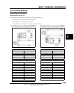
Figure 17
Figure 18
WARNING
CHARGE THE SHOCK USING NITROGEN GAS
ONLY. DO NOT FILL WITH ANY OTHER GASES.
Doing so compromises the performance of the shock
and may be EXTREMELY DANGEROUS!
Figure 19