


C2924M (4/05) 19
4. Use 100-ohm twisted pair cabling to wire the device to the enclosed connector assembly. The decision to use shielded cable depends on
your installation; shielded cable may be optional.
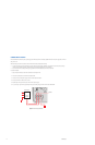
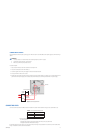
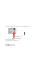
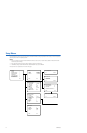
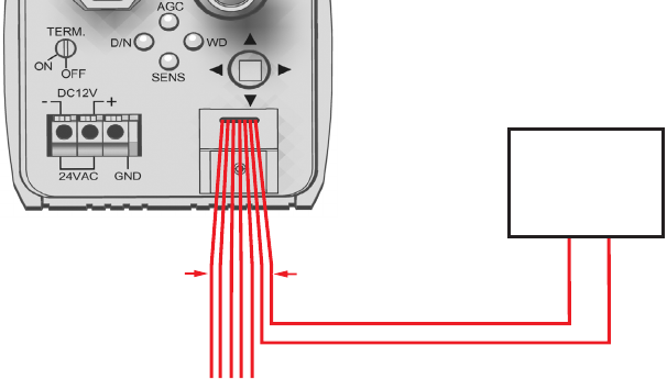
Figure 8. Day/Night Filter Control Configuration
5. Wire the camera to the external switch as follows:
• Pin 7 (brown, signal input) to the (+) lead on the external switch.
• Pin 6 (black, ground) to the (–) lead on the external switch.
• Shielded cable only: Connect the shield to either pin 3 (black, ground) or pin 6 (black, ground).
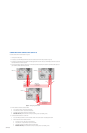
6. Change DAY & NIGHT to EXT. (external) on the EXPOSURE SETTINGS menu.
7. Configure the external switch as follows:
• Open or High: Camera operates in AUTO mode.
• Short or Low: Camera operates in BW mode.
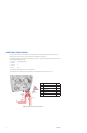
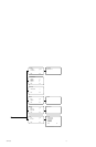
INPUT (7)
GND (6)
EXTERNAL SWITCH
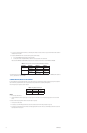
PIN 7
PIN 1