


C2924M (4/05) 15
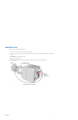
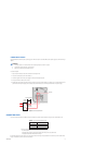
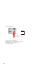
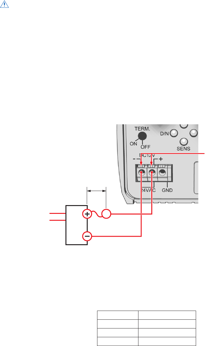
CONNECTING DC POWER
The CCC1390H Series camera requires a power supply of 12 VDC ±15% (10.2 to 13.8 VDC). Make sure the power supply has a minimum rating of
390 mA.
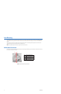
To connect DC power:
1. Strip at least 0.4 inches (10 mm) of the insulation from each power wire.
2. Press and hold the button over the hole marked (–).
3. Insert the negative wire from the power supply into the hole and release the button.
4. Gently pull the wire to make sure it is secure.
5. Repeat steps 2 through 4 for the positive wire from the power supply. Use the hole marked (+). For safety, add a 1.0 A slow blow fuse to the
positive wire from the power supply. The fuse should be less than 4 inches (10 cm) from the positive terminal on the power supply.
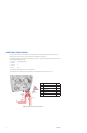
Figure 5.
Connecting DC Power
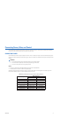
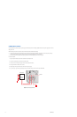
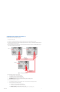
CONNECTING VIDEO
Connect a coaxial video cable to the BNC connector on the back of the camera. Refer to Table B for the type of video coaxial cable to use.
*Cable requirements:
75 ohms impedance
All-copper center conductor; steel-center conductor cable may result in poor performance
All-copper braided shield with 95% braid coverage
If white spots appear in the video image, one or more pixels on the camera imager may be defective. This condition is common to CCD camera
imagers. To correct this condition, refer to
Pixel Correction
.
WARNINGS:
• For safety, include a 1.0 A slow blow fuse when connecting DC power, as shown in Figure 5.
• The DC power supply must be UL- and CE-certified.
• Make sure you wire the power polarity correctly.
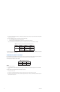
Table B. Video Coaxial Cable Requirements
Cable Type* Maximum Distance
RG59/U 750 ft (229 m)
RG6/U 1,000 ft (305 m)
RG11/U 1,500 ft (457 m)
+12
VDC
GND
4 INCH (10 CM) MAX.
1.0 A FUSE
(SLOW BLOW)
POWER
SUPPLY
INPUT
BUTTONS