


C2924M (4/05) 17
CONNECTING SERIAL CONTROL (PELCO D/PELCO P)
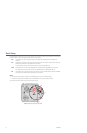
To connect serial control to the camera (refer to Figure 7):
1. Turn off power to the camera.
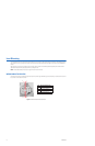
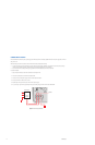
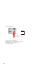
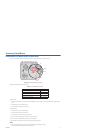
2. If necessary, use a small Phillips screwdriver to remove the connector cover from the rear panel (refer to Figure 6).
3. If necessary, plug the external control connector assembly (supplied) into the camera. Then use a small Phillips screwdriver to secure the
assembly connector cover to the rear panel.
4. Use 100-ohm twisted pair cabling to wire each pair on the enclosed connector assembly. The decision to use shielded cable depends on
your installation; shielded cable may be optional.
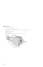
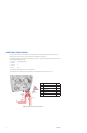
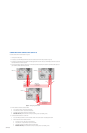
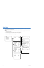
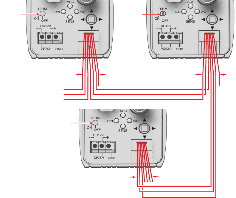
Figure 7. Configuring a Serial Chain
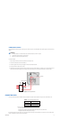
5. Wire the camera to the control device as follows:
• Pin 1 (red, RX+) to the TX+ lead on the control device.
• Pin 2 (white, RX–) to the TX– lead on the control device.
• Pin 3 (black, ground) to the ground lead on the control device.
• Shielded cable only: Connect the shield to either pin 3 (black, ground) or pin 6 (black, ground).
6. To connect additional cameras in a serial chain:
a. Use a small flat tip screwdriver to turn the termination switch on this camera to OFF. The default position is ON.
b. Wire this camera to the next camera as follows:
• Pin 4 (red, TX+) to pin 1 (red, RX+) on the next camera.
• Pin 5 (white, TX–) to pin 2 (white, RX–) on the next camera.
• Pin 6 (black, ground) to pin 3 (black, ground) on the next camera.
• Shielded cable only: Connect the shield to either pin 3 (black, ground) or pin 6 (black, ground).
TERM = OFF TERM = OFF
TERM = ON
GND (6) TO (3)
TX- (5) TO RX- (2)
TX+ (4) TO RX+ (1)
GND (6) TO (3)
TX- (5) TO RX- (2)
TX+ (4) TO RX+ (1)
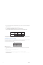
PIN 7
PIN 1
RX+ (1)
RX- (2)
GND (3)
PIN 7
PIN 1
PIN 1
PIN 7