


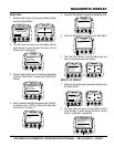
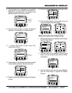
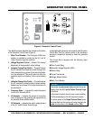
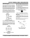
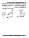
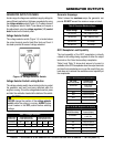
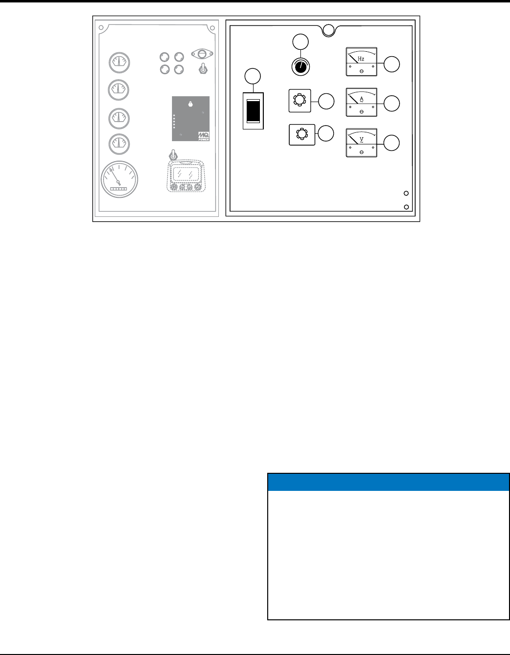
GENERATOR CONTROL PANEL
Figure 5. Generator Control Panel
OFF
W
U
V
OFF
W-U
V-W
U-V
DECREASE
INCREASE
1
AUTO
MANUAL
OFF/RESET
LOWOILPRESSURE
HIGHCOOLANTTEMPERATURE
OVERCRANK
OVERSPEED
ENGINERUNNING
MOOOOO-20001Q
2
3
4
6
7
5
The definitions below describe the controls and functions
of the Generator Control Panel (Figure 5).
1. —This three-pole, 400A main
breaker is provided to protect the the U,V, and W
Output Terminal Lugs from overload.
2. — Allows ±15% manual
adjustment of the generator’s output voltage.
3. — This switch allows
the AC ammeter to indicate the current flowing to the
load connected to any phase of the output terminals,
or to be switched off. This switch does not effect the
generator output in any fashion, it is for current reading
only.
4. — This switch allows
the AC voltmeter to indicate phase to phase voltage
between any two phases of the output terminals or to
be switched off.
5. — Indicates the output frequency
in hertz (Hz). Normally 60 Hz.
6. AC Ammeter — Indicates the amount of current the
load is drawing from the generator per leg selected by
the ammeter phase-selector switch.
7. — Indicates the output voltage present
at the U,V, and W Output Terminal Lugs.
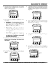
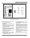
Located behind the generator control panel is the Generator
Control Box. This box contains some of the necessary
electronic components required to make the generator
function.
The Control Box is equipped with the following major
components:
Over-Current Relay
Automatic Voltage Regulator (AVR)
Starter Relay
Current Transformer
Voltage Selector Switch
Main Circuit Breaker
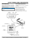
NOTICE
Remember the overcurrent relay monitors the current
flowing from the
to the load.
In the event of a short circuit or over current condition,
it will automatically trip the 400 amp main breaker.
To restore power to the Output Terminal Panel, press
the reset button on the overcurrent relay and place the
main circuit breaker in the closed position (ON).