


DIAGNOSTIC DISPLAY
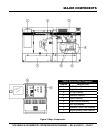
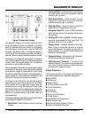
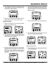
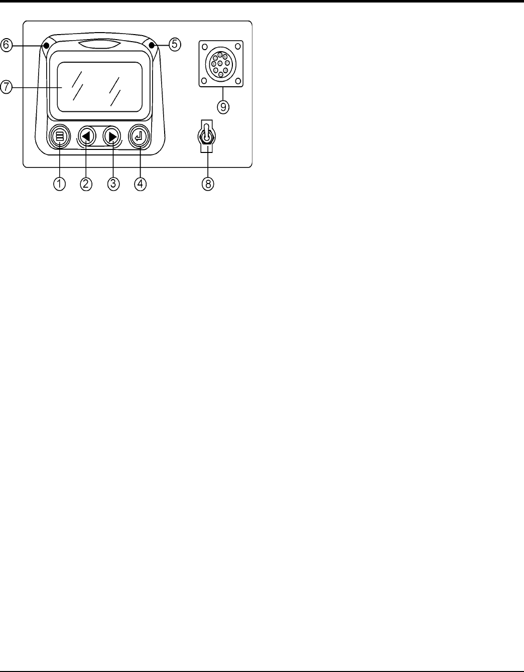
Figure 4. Diagnostic Display
The diagnostic display panel located inside the control
box on the generator (Figure 4) is designed to meet the
needs for instrumentation and control of electronically
controlled engine communication using the SAEJ1939
Controller Area Network (CAN). This diagnostic display is
a multifunction tool that enables equipment operators to
view many different engine parameters and service codes.
The keypad on the diagnostic display panel is a capacitive
touch sensing system. There are no mechanical switches
to wear or stick. This keypad (display unit) will operate in
extreme hot or cold weather conditions.
Other components in the system are microprocessor-based
components for displaying critical engine data broadcast
by an electronic engine or transmission’s Engine Control
Unit (ECU): engine RPM, oil pressure, coolant temperature,
system voltage, etc., and a combination audible alarm and
relay unit for warning and shutdown annunciation.
The Engine Control Unit (ECU) used with this generator
diagnosis engine faults that arise with the the engine
control system and the engine itself. Engine faults can
be determined by viewing the Diagnostic Trouble Codes
(Active Fault Codes) which are displayed on the Diagnostic
Display Panel. See the John Deere Engine Operator’s
Manual for a complete listing of active fault codes and
countermeasures.
The following definitions describe the controls and functions
of the Diagnostic Display Panel (Figure 4).
1. Press this button to enter or exit menu
screens.
2. Press this button to scroll through
the screen either moving the parameter selection
toward the left or upward.
3. Press this button to scroll
through the screen either moving the parameter
selection toward the right or downward.
4. Press this button to select the
parameter that is highlighted on the screen.
5. When lit (RED) indicates a
major fault has occured. This condition will shudown
the generator.
6. When lit (AMBER), indicates a engine
parameter has exceeded its limits (minor fault). The
generator will still run in this condition.
7. Graphical backlight LCD screen.
Back lighting is controlled via menu or external
dimmer potentiometer. The display can show either a
single parameter or a quadrant display showing four
parameters simultaneously.
8. When placed in the ON position,
will activate the diagnostic display panel.
9. Controller Area
Network connector. This connector outputs diagnostic
error codes. Connect a scanner or similar device into
this connector to read error codes.
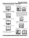
Display Parameters
The following are some of the engine and transmission
parameters displayed on the diagnostic disply panel.
Engine RPM’s
Engine Hours
System Voltage
% Engine Load at current RPM
Coolant Temperature
Oil Pressure
Fuel Economy
Current Fuel Consumption
Throttle Position
Engine Manifold Air Temperature
Active Service Codes
Set Units for Display (English or Metric)
English Configuration Parameters.