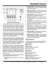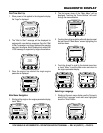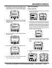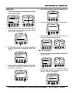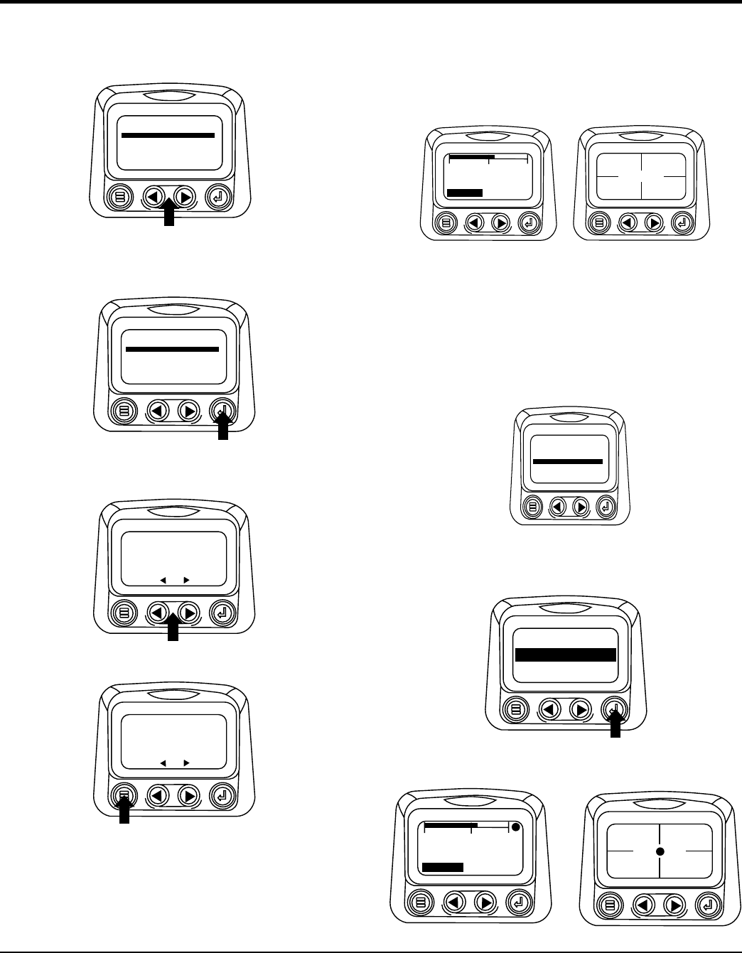
2. The main menu will pop up on the display. Use the
“Arrow Buttons” to scroll through the menu until the
“Engine Configuration” menu item has been highlighted
.
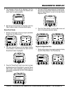
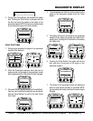
3. Once the “Engine Configuration” menu item has been
highlighted touch the “Enter Button” to view the engine
configuration data.
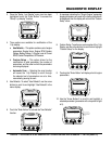
4. Use the “Arrow Buttons” to scroll through the engine
configuration data.
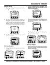
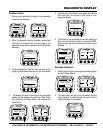
5. Touch the “Menu Button” to return to the main menu.
6. Touch the “Menu Button” to exit the Main menu and
return to the engine parameter display.
GOTO1-UPDISPLAY
STOREDCODES
ADJUSTBACKLIGHT
SETUP1-UPDISPLAY
SETUP-4-UPDISPLAY
SELECTUNITS
ENGINECONFG
GOTO1-UPDISPLAY
STOREDCODES
ADJUSTBACKLIGHT
SETUP1-UPDISPLAY
SETUP-4-UPDISPLAY
SELECTUNITS
ENGINECONFG
ENGINE SPEEDPT 1
1800 RPM
MORE
ENGINE SPEEDPT 1
1800 RPM
MORE
Auxiliary Gage Fault
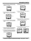
1. During normal operation the single or four parameter
screen will be displayed.
2. The PVA Series of auxiliary gages can be attached to
the PowerView. These auxiliary gages communicate
with the Modbus master PowerView via a daisy-chained
RS-485 port. If at any time during system initialization
or normal operation an auxiliary gage should fail, the
single or four parameter screen will be replaced with
the “MLink Gage Fault” message.
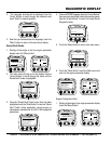
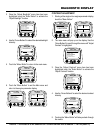
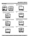
3. To acknowledge and “Hide” the fault and return to the
single or four parameter display, touch the “Enter
Button.
4. The display will return to the single or four parameter
screen.
COOL
1800 RPM
0
1500
3000
TEMP
ENG RPM
98%
14.2
57 PSI
1000 RPM
LOADRPM
BATTVOLT
ENGRPM
OILPRES
ENGINEOILPRESSURE
GAGENOTRESPONDING
1ofx
HIDE
ENGINEOILPRESSURE
GAGENOTRESPONDING
1ofx
HIDE
COOL
1800 RPM
0
1500
3000
TEMP!
ENG RPM
!
98%
14.2
!
57 PSI
1000 RPM
LOADRPM
BATTVOLT
ENGRPM
OILPRES
!
DIAGNOSTIC DISPLAY


