


69
Reassembly
20 690 01 Rev. F KohlerEngines.com
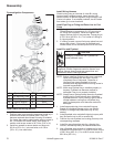
1. Check to make sure there are no nicks or burrs on
sealing surfaces of cylinder head or crankcase.
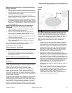
2. If engine uses a drain back check ball, install it into
keyhole slot in top of crankcase.
3. Install a new cylinder head gasket.
4. Install cylinder head and start six screws. Install thick
washer on screw closest to exhaust port.
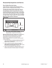
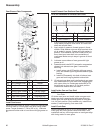
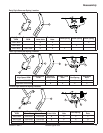
5. Using torque sequence shown, torque cylinder head
screws in two stages; initially to 20.5 N·m
(180 in. lb.), and fi nally to 41.0 N·m (360 in. lb.).
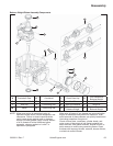
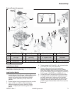
Install Rocker Arms and Push Rods
NOTE: Installation and seating of push rods into cam
lever recesses during this sequence is critical.
Position engine with cylinder head up if possible,
to aid with proper installation of push rods and
rocker arms, and adjusting valve lash.
NOTE: If being reused, push rods should always be
installed in their original position.
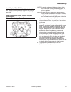
1. Position push rod guide plates on cylinder head with
extruded edges down over push rod bores. Secure
by installing rocker arm pivot studs. Torque studs to
13.5 N·m (120 in. lb.).
2. Apply grease to contact surfaces of rocker arms and
adjusting nuts and install them onto pivot studs.
3. Note mark or tag identifying push rod as either
intake or exhaust. Apply grease to ends of push
rods. Insert push rods into push rod bores and seat
lower end into dimpled recess of cam levers. It may
be necessary to lift or shift lower end of push rod
slightly, and feel rod seats into recess. Once seated,
hold it in place as you position rocker arm. Push rod
must stay in recess while rocker arms are positioned
and adjusted.
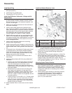
4. With engine at TDC of compression stroke, insert
correct size fl at feeler gauge (see below) between
appropriate valve stem and rocker arm. Tighten
adjustment nut with a wrench until a slight drag is felt
on feeler gauge. Hold nut in position and torque set
screw (T15 Torx drive) to 5.5 N·m (50 in. lb.). To
prevent damage to nut, torque Torx screw only.
Perform adjustment procedure on other valve.
Clearance Specifi cations-Valve
Intake Valve 0.127 mm (0.005 in.)
Exhaust Valve 0.178 mm (0.007 in.)
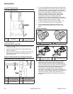
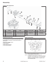
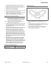
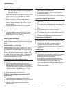
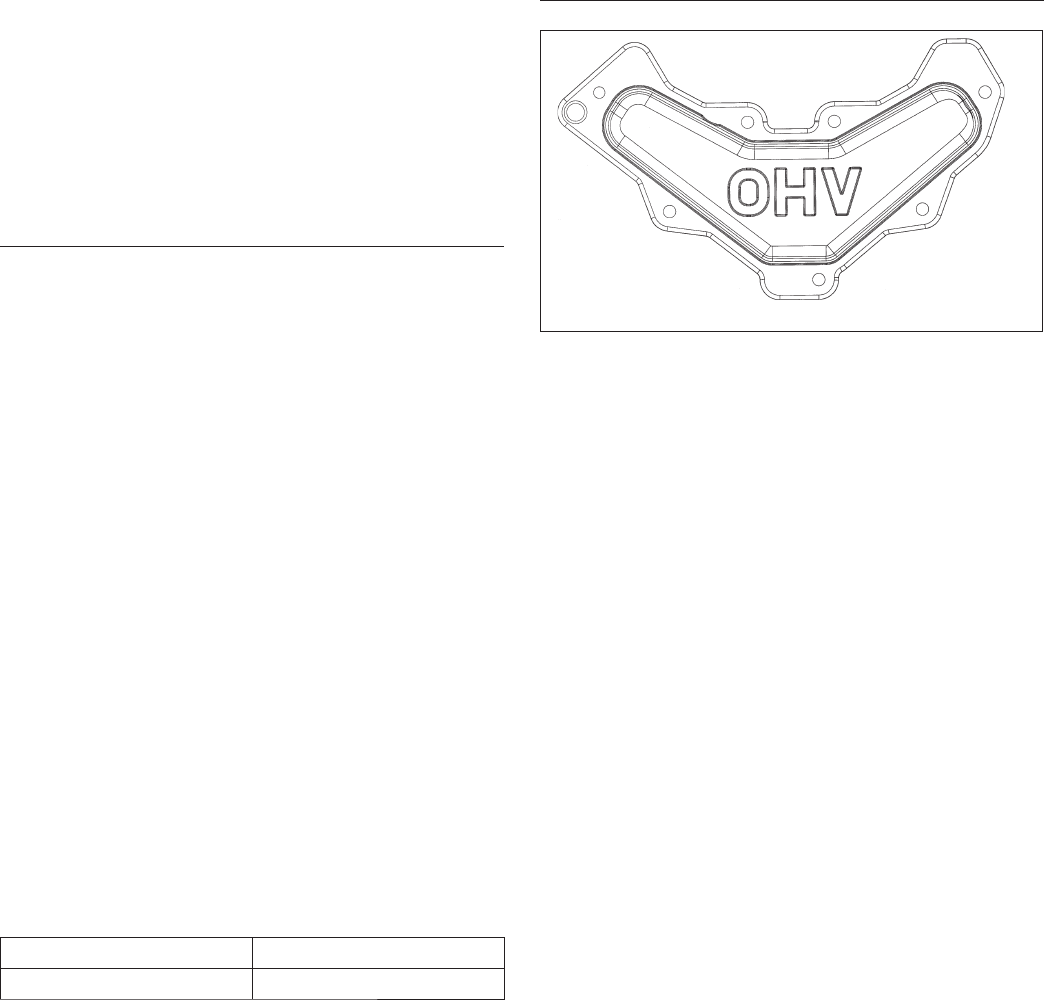
Install Valve Cover
Valve Cover Torque Sequence
7
5
2
3
4
1
6
1. Make sure sealing surfaces of valve cover and
cylinder head are clean, and free of any nicks or
burrs.
2. Install a new valve cover gasket, followed by valve
cover. Position any brackets mounted on valve cover
and start seven mounting screws.
3. Torque valve cover screws to 11.0 N·m (95 in. lb.)
into new holes, or 7.5 N·m (65 in. lb.) into used
holes, using sequence shown.