42
Electrical System
KohlerEngines.com 20 690 01 Rev. F
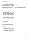
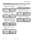
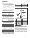
9/15 Amp Regulated Battery Charging System
NOTE: Zero ohmmeter on each scale before testing to
ensure accurate readings. Voltage tests should
be made with engine running at full throttle with
no load. Battery must be fully charged.
To test charging system for no charge to battery:
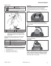
1. Insert an ammeter in B+ lead from rectifi er-regulator.
With engine running at 3600 RPM and B+ (at
terminal on rectifi er-regulator) to ground using a DC
voltmeter.
If voltage is 13.8 volts or more, place a minimum
load of 5 amps (turn on lights if 60 watts or more, or
place a 2.5 ohm, 100 watt resistor across battery
terminals) on battery to reduce voltage. Observe
ammeter.
Condition Conclusion
Charge rate increases
when load is applied.
Charging system is OK
and battery was fully
charged.
Charge rate does not
increase when load is
applied.
Test stator and rectifi er-
regulator (steps 2 and 3).
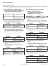
2. Remove connector from rectifi er-regulator. With
engine running at 3600 RPM, measure AC voltage
across stator leads using an AC voltmeter.
Condition Conclusion
Voltage is 28 volts or
more.
Stator is OK. Rectifi er-
regulator is faulty; replace.
Voltage is less than 28
volts.
Stator is faulty; replace.
Test stator further using an
ohmmeter (steps 3 and 4).
3. With engine stopped, measure resistance across
stator leads using an ohmmeter.
Condition Conclusion
Resistance is 0.1/0.2
ohms.
Stator is OK.
Resistance is infi nity
ohms.
Stator is open; replace.
4. With engine stopped, measure resistance from each
stator lead to ground using an ohmmeter.
Condition Conclusion
Resistance is infi nity ohms
(no continuity).
Stator is OK (not shorted
to ground).
Resistance (or continuity)
measured.
Stator leads are shorted to
ground; replace.
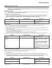
To test charging system for battery continuously charging
at high rate:
1. With engine running at 3600 RPM, measure voltage
from B+ lead to ground using a DC voltmeter.
Condition Conclusion
Voltage is 14.7 volts or
less.
Charging system is OK.
Battery is unable to hold
charge; service or replace.
Voltage is more than 14.7
volts.
Faulty rectifi er-regulator;
replace.
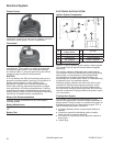
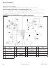
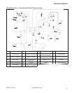
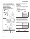
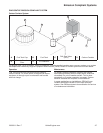
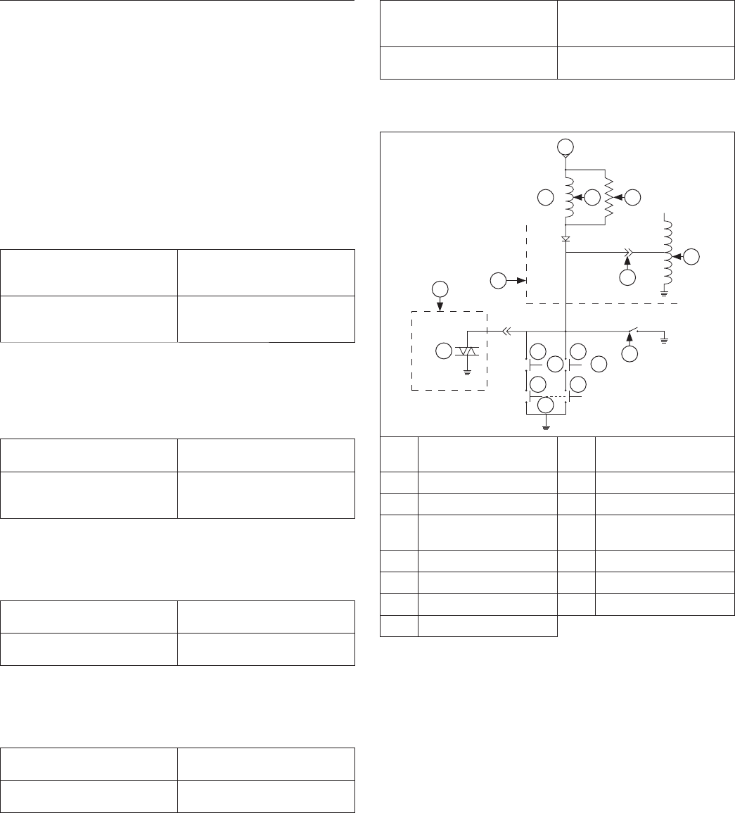
BLADE STOP STATOR BRAKE CIRCUIT
Wiring Diagram-Blade Stop Stator Brake Circuit
A
E
H
B
I
J
L
K
K
N
M
J
C D
G
F
O
A 12V Switched Power B
Stator Brake
Relay Coil
C 90 Ω D 680 Ω
E Engine F Kill
G CDI Ignition H
Reverse Mow Module
(OEM Supplied)
I TRIAC J NO
K NC L PTO
M Brake N Seat
O Key Switch
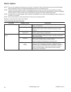
Blade stop stator brake circuit is provided as a safety
feature to ensure application can meet ANSI (American
National Standards Institute) application blade stop
requirements.
Circuit is activated if operator gets off of seat of
application while mower blade system is activated or in
certain reverse mow conditions.
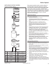
Circuit is activated by taking ignition shutdown (kill) lead
to ground. This action turns on stator-brake relay which
shorts charging AC stator leads to produce a magnetic
fi eld that will counter or resist rotation of fl ywheel. This
added resistance to rotation decreases amount of time it
takes for application deck blades to come to a full stop.


