


55
Disassembly/Inspection and Service
20 690 01 Rev. F KohlerEngines.com
Inspection and Service
Carefully inspect valve mechanism parts. Inspect valve
springs and related hardware for excessive wear or
distortion. Check valves and valve seats for evidence
of deep pitting, cracks, or distortion. Check running
clearance between valve stems and guides.
Hard starting, or loss of power accompanied by high
fuel consumption, may be symptoms of faulty valves.
Although these symptoms could also be attributed to
worn rings, remove and check valves fi rst. After removal,
clean valve heads, faces, and stems with a power wire
brush. Then, carefully inspect each valve for defects
such as warped head, excessive corrosion, or worn stem
end. Replace valves found to be in bad condition.
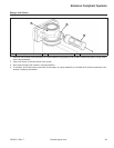
Valve Guides
If a valve guide is worn beyond specifi cations, it will not
guide valve in a straight line. This may result in burned
valve faces or seats, loss of compression, and excessive
oil consumption.
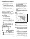
To check valve guide-to-valve stem clearance,
thoroughly clean valve guide and, using a split-ball
gauge, measure inside diameter. Then, using an outside
micrometer, measure diameter of valve stem at several
points on stem where it moves in valve guide. Use
largest stem diameter to calculate clearance. If intake
clearance exceeds 0.038/0.076 mm (0.0015/0.0030
in.) or exhaust clearance exceeds 0.050/0.088 mm
(0.0020/0.0035 in.), determine whether valve stem or
guide is responsible for excessive clearance.
Maximum (I.D.) wear on intake valve guide is 6.135 mm
(0.2415 in.) while 6.160 mm (0.2425 in.) is maximum
allowed on exhaust guide. Guides are not removable. If
guides are within limits but valve stems are worn beyond
limits, replace valves.
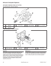
Valve Seat Inserts
Hardened steel alloy intake and exhaust valve seat
inserts are press fi tted into cylinder head. Inserts are
not replaceable, but they can be reconditioned if not too
badly pitted or distorted. If seats are cracked or badly
warped, cylinder head should be replaced.
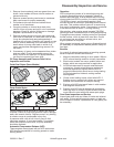
Recondition valve seat inserts following instructions
provided with valve seat cutter being used. Final cut
should be made with an 89° cutter as specifi ed for valve
seat angle. With proper 45° valve face angle, and valve
seat cut properly (44.5° as measured from center line
when cut 89°) this would result in desired 0.5° (1.0° full
cut) interference angle where maximum pressure occurs
on valve face and seat.
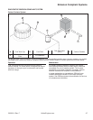
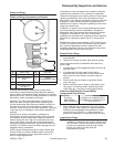
Lapping Valves
Reground or new valves must be lapped in, to provide
a good seal. Use a hand valve grinder with suction
cup for fi nal lapping. Lightly coat valve face with fi ne
grade of grinding compound, then rotate valve on seat
with grinder. Continue grinding until smooth surface is
obtained on seat and on valve face. Thoroughly clean
cylinder head in soap and hot water to remove all traces
of grinding compound. After drying cylinder head, apply
a light coating of engine oil to prevent rusting.
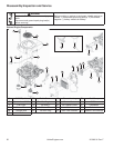
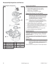
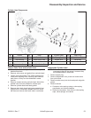
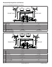
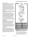
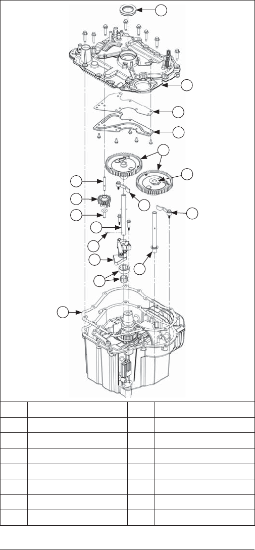
Cam/Closure Plate Components
G
F
H
L
G
O
N
K
J
I
M
P
B
C
D
E
A
A Oil Seal B Closure Plate
C Oil Passage Cover D Gasket
E Cam Gears F Thrust Washer
G Cam Levers H Cam Shaft (Exhaust)
I Closure Plate Gasket J Gerotor Gears
K Oil Pump L Cam Shaft Pin
M Cam Shaft (Intake) N Regulating Pin
O Governor Gear P Governor Gear Shaft
Remove Closure Plate
1. Remove screws securing closure plate to crankcase.
Note location and position of any attached clips or
clamps.
2. A gasket is used between closure plate and
crankcase. If necessary, carefully tap on bosses for
starter or oil fi lter with a soft-faced mallet to loosen.
Do not pry on gasket surfaces of crankcase or oil
pan, as this can cause damage resulting in leaks.
3. Remove closure plate assembly and gasket.