61
Disassembly/Inspection and Service
20 690 01 Rev. F KohlerEngines.com
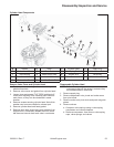
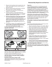
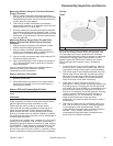
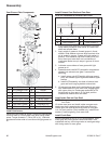
Measuring Balance Weight to Crankshaft Eccentric
Ring(s) Clearance
1. Use an inside micrometer, telescoping gauge, or
bore gauge and measure inside diameter of balance
weight bearing surface. Take two measurements 90°
to each other on each weight.
2. Then use an outside micrometer and measure
across each eccentric on crankshaft. Again take two
measurements 90° to each other.
3. Running clearance is eccentric diameter subtracted
from balance weight bearing diameter (step 1 minus
step 2). If measurements are outside maximum wear
limits listed in Specifi cations, affected component(s)
must be replaced.
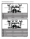
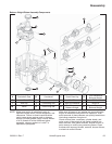
Measuring Balance Weight Guide Pin and Guide
Shoe-to-Closure Plate Guide Channel Running
Clearance
1. Use an outside micrometer and measure outside
width of balance weight guide shoe.
2. Use an inside micrometer, telescoping gauge or
similar tool and measure width of guide channel in
closure plate. Record these dimensions.
3. Use an outside micrometer again and measure O.D.
of balance weight guide pin.
4. Use a split ball gauge or dial calipers and measure
I.D. of corresponding hole in guide shoe. Record
these dimensions.
If any of measurements taken are outside maximum
wear limits listed in Specifi cations, affected
component(s) must be replaced.
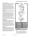
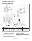
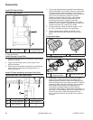
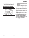
Remove Governor Cross Shaft
1. Remove hitch pin and washer located on outside of
governor cross shaft.
2. Slide shaft inward and remove it through inside of
crankcase. Be careful not to lose small washer in
inside portion of shaft.
Remove PTO and Flywheel Side Oil Seals
Use a seal puller to remove PTO and fl ywheel side oil
seals.
Crankcase
Inspection and Service
Check all gasket surfaces to make sure they are free of
gasket fragments and deep scratches or nicks.
Check cylinder wall for scoring. In severe cases,
unburned fuel can wash necessary lubricating oil off
piston and cylinder wall. Piston rings make metal to
metal contact with wall, causing scuffi ng and scoring.
Scoring of cylinder wall can also be caused by localized
hot spots from blocked cooling fi ns or from inadequate or
contaminated lubrication.
If cylinder bore is scored, worn, tapered, or out-of-round,
resizing may be possible. Use an inside micrometer or
telescoping gauge to determine amount of wear (refer to
specifi cations). If wear exceeds published limits, a 0.08
mm (0.003 in.) oversize piston is available. If cylinder
will not clean up at 0.08 mm (0.003 in.) oversize, a short
block or replacement engine will need to be considered.
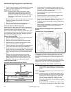
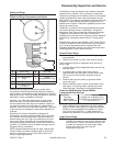
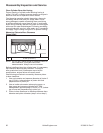
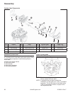
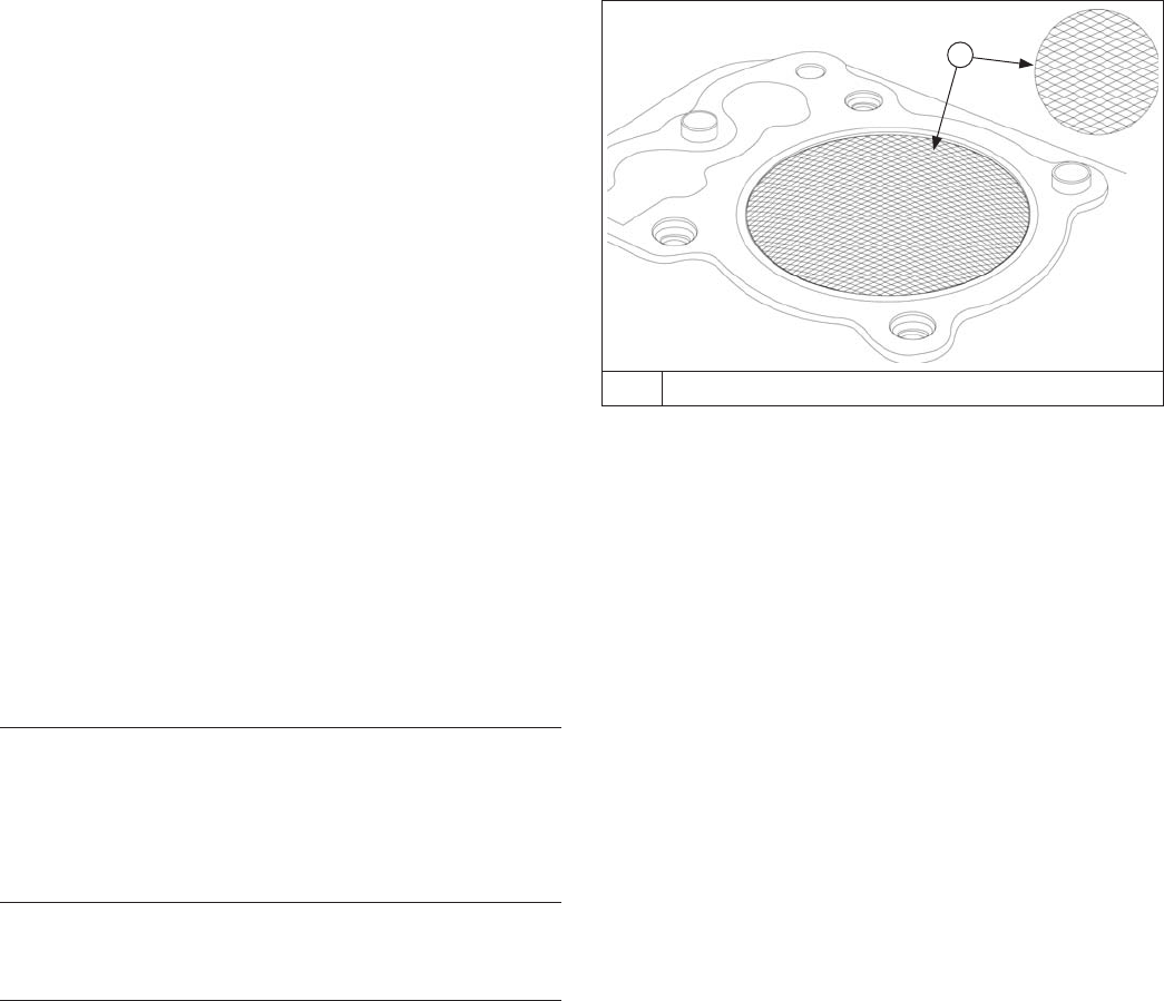
Honing
Detail
A
A 23°-33° Crosshatch
While most commercially available cylinder hones can
be used with either portable drills or drill presses, use
of a low speed drill press is preferred as it facilitates
more accurate alignment of bore in relation to crankshaft
counter bore. Honing is best accomplished at a drill
speed of about 250 RPM and 60 strokes per minute.
After installing coarse stones in hone, proceed as
follows:
1. Lower hone into bore and, after centering, adjust it
so stones are in contact with cylinder wall. Use of a
commercial cutting-cooling agent is recommended.
2. With lower edge of each stone positioned even with
lowest edge of bore, start drill and honing process.
Move hone up and down while resizing to prevent
formation of cutting ridges. Check size frequently.
Make sure bore is cool when measuring.
3. When bore is within 0.064 mm (0.0025 in.) of
desired size, remove coarse stones and replace with
burnishing stones. Continue with burnishing stones
until within 0.013 mm (0.0005 in.) of desired size and
then use fi nish stones (220-280 grit) and polish to
fi nal size. A crosshatch should be observed if honing
is done correctly. Crosshatch should intersect at
approximately 23°-33° off horizontal. Too fl at an
angle could cause rings to skip and wear
excessively, too steep an angle will result in high oil
consumption.
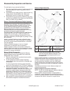
4. After honing, check bore for roundness, taper, and
size. Use an inside micrometer, telescoping gauge,
or bore gauge to take measurements. These
measurements should be taken at three locations in
cylinder – at top, middle, and bottom. Two
measurements should be taken (perpendicular to
each other) at 3 different locations.


