


59
Disassembly/Inspection and Service
20 690 01 Rev. F KohlerEngines.com
Piston and Rings
Inspection
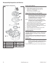
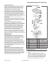
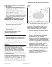
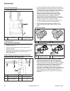
Piston and Rings Components and Details
A Piston Ring B End Gap
C Identifi cation Mark D Piston
E
Top Compression
Ring
F
Center
Compression Ring
G Rails H Expander
I
Oil Control Ring
(3 Piece)
A
B
C
D
E
F
G
I
H
Scuffi ng and scoring of pistons and cylinder walls
occurs when internal temperatures approach welding
point of piston. Temperatures high enough to do this are
created by friction, which is usually attributed to improper
lubrication, and/or overheating of engine.
Normally, very little wear takes place in piston boss-
piston pin area. If original piston and connecting rod
can be reused after new rings are installed, original pin
can also be reused, but new piston pin retainers are
required. Piston pin is part of piston assembly; if pin boss
or pin are worn or damaged, a new piston assembly is
required.
Ring failure is usually indicated by excessive oil
consumption and blue exhaust smoke. When rings fail,
oil is allowed to enter combustion chamber where it is
burned along with fuel. High oil consumption can also
occur when piston ring end gap is incorrect because
ring cannot properly conform to cylinder wall under this
condition. Oil control is also lost when ring gaps are not
staggered during installation.
When cylinder temperatures get too high, lacquer and
varnish collect on pistons causing rings to stick which
results in rapid wear. A worn ring usually takes on a
shiny or bright appearance.
Scratches on rings and pistons are caused by abrasive
material such as carbon, dirt, or pieces of hard metal.
Detonation damage occurs when a portion of fuel charge
ignites spontaneously from heat and pressure shortly
after ignition. This creates two fl ame fronts that meet and
explode to create extreme hammering pressures on a
specifi c area of piston. Detonation generally occurs from
using low octane fuels.
Preignition or ignition of fuel charge before timed spark
can cause damage similar to detonation. Preignition
damage is often more severe than detonation damage.
Preignition is caused by a hot spot in combustion
chamber from sources such as glowing carbon deposits,
blocked fi ns, improperly seated valve, or wrong spark
plug.
Replacement pistons are available in STD and 0.08 mm
(0.003 in.) oversize, which include new rings and piston
pins. Service replacement piston ring sets are also
available separately. Always use new piston rings when
installing pistons. Never reuse old rings.
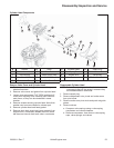
Remove Piston Rings
1. Remove top and center compression rings using a
ring expander.
2. Remove oil control ring rails, then remove spacer.
Some important points to remember when servicing
piston rings:
1. Cylinder bore must be deglazed before service ring
sets are used.
2. If cylinder bore is within wear limits (refer to
Specifi cations) and old piston is within wear limits,
free of score or scuff marks, old piston may be
reused.
3. Remove old rings and clean up grooves. Never
reuse old rings.
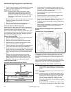
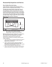
4. Before installing rings on piston, place each of top
two rings in its running area in cylinder bore and
check end gap. Compare to listed specifi cations.
Clearance Specifi cations-Top and Middle
Compression Ring End Gap
New Bore
Top Ring
Middle Ring
Max. Used Bore
0.15/0.40 mm (0.006/0.016 in.)
0.30/0.55 mm (0.012/0.022 in.)
0.77 mm (0.030 in.)
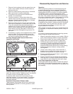
5. After installing new compression (top and middle)
rings on piston, check piston-to-ring side clearance.
Maximum recommended side clearance for each
ring is 0.04 mm (0.0016 in.). If side clearance is
greater than specifi ed, a new piston must be used.
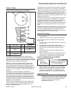
Install Piston Rings
NOTE: Rings must be installed correctly. Ring
installation instructions are usually included with
new ring sets. Follow instructions carefully. Use
a piston ring expander to install rings. Install
bottom (oil control) ring fi rst and top
compression ring last.