


28
Fuel System
KohlerEngines.com 20 690 01 Rev. F
Starting an Engine Equipped with Unitized Throttle
and Choke Control
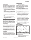
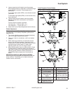
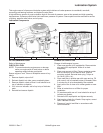
Starting Throttle Control Details
A
A Cold Engine or Warm Engine
NOTE: Do not crank engine continuously for more than
10 seconds at a time. If engine does not start,
allow a 60 second cool down period between
starting attempts. Failure to follow these
guidelines can burn out starter motor.
NOTE: If engine develops suffi cient speed to disengage
starter but does not keep running (a false start),
engine rotation must be allowed to come to a
complete stop before attempting to restart
engine. If starter is engaged while fl ywheel is
rotating, starter pinion and fl ywheel ring gear
may clash, resulting in damage to starter.
If starter does not turn engine over, shut starter off
immediately. Do not make further attempts to start
engine until condition is corrected. Do not jump start
using another battery. See your Kohler authorized dealer
for trouble analysis.
1. For a Cold or Warm Engine – Place throttle/choke
control into fast/choke ON position. This will also
place choke into ON position.
2. Make sure equipment is in neutral.
3. Activate starter switch. Release switch as soon as
engine starts.
4. For Operation – After engine starts, move throttle/
choke control from fast/choke ON position and set
desired engine operating speed (between slow and
fast position).
High Speed (RPM) Adjustment
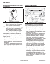
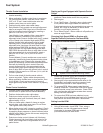
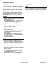
Speed Control Bracket Details
A
A
A Speed Control Bracket Mounting Screw
Recommended maximum no-load high speed (RPM)
for most engines is 3300 RPM. Actual high speed
(RPM) depends on application. Refer to equipment
manufacturer’s instructions for specifi c information.
1. Make sure throttle cable is adjusted properly (see
Throttle Cable Adjustment).
2. Start engine and allow it to warm up. Place throttle
control lever into fast or high speed position. Turn
choke adjusting screw out/counterclockwise, so
there is clearance from choke lever, and that contact
cannot occur during Step 4.
3. Early Models: Early models use a single alignment
hole to set engine RPM. Align hole in throttle lever
with hole in speed control bracket by inserting a
pencil or 6.35 mm (1/4 in.) drill bit.
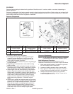
Later Models: Later models utilize a new design
control assembly, identifi ed by two opposing
alignment holes (close to throttle lever pivot), instead
of one. Based upon intended high speed (RPM)
setting, throttle cable adjustment must be made
matching hole in control lever with appropriate
alignment hole. Use lower (left side) hole for high-
speed settings 3000 RPM and above. Use upper
(right side) hole for high-speed settings less than
3000 RPM. Move throttle lever to align hole in lever
with appropriate hole in control bracket. Insert a
pencil or a 6.35 mm (1/4 in) drill bit to hold in
position.
Current Models: Current models use a new control
assembly, identifi ed by three alignment holes (close
to throttle lever pivot). Based upon intended high-
speed (RPM) setting, throttle cable adjustment must
be made by matching hole in control lever with
correct alignment hole. Use appropriate hole for
corresponding high-speed settings. Move throttle
lever to align hole in lever with correct hole in control
bracket. Insert a pencil or a 6.35 mm (1/4 in.) drill bit
to hold in position.