


56
Disassembly/Inspection and Service
KohlerEngines.com 20 690 01 Rev. F
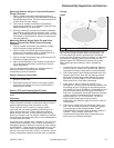
4. If wiring harness needs to be separated from closure
plate, pry open clamps and pull out through slot.
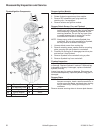
Disassemble Closure Plate
NOTE: Governor gear is held onto shaft by small
molded tabs in gear. When gear is removed
these tabs are destroyed and gear must be
replaced. Governor gear removal is required for
closure plate disassembly and cleaning of oil
passages.
1. Remove governor gear and regulating pin assembly.
Gently pry upward using blades of two small
screwdrivers.
2. Remove screws securing oil passage cover to
closure plate. Remove cover and gasket.
Governor Gear and Shaft Inspection
Inspect governor gear teeth. Look for any evidence of
worn, chipped, or cracked teeth. If one or more of these
problems is noted, replace governor gear.
Gear is held onto governor shaft by molded tabs, which
are damaged when gear is removed. Never reuse gear
once it has been pulled from shaft. Replace governor
shaft only if it is damaged or worn.
Remove Governor Shaft
1. Remove blower housing, fl ywheel, and cooling fan.
2. Remove stator and crankshaft key.
3. Remove closure plate screws and closure plate.
4. Rotate engine to top dead center aligning timing
marks on crankshaft and cam gears.
5. Remove governor gear assembly and regulating pin
from closure plate with two small screwdrivers.
6. Locate governor pin from fl ywheel side. With a small
punch, drive pin out of closure plate. This could also
be done with a press. Do not remove governor pin
with a vise grip or pliers, you may damage closure
plate.
7. Remove any old gasket material from mating
surfaces of crankcase and closure plate. Use an
aerosol gasket remover to help loosen any old
gasket material. Do not scrape surfaces, as any
scratches, nicks, or burrs can result in leaks.
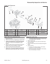
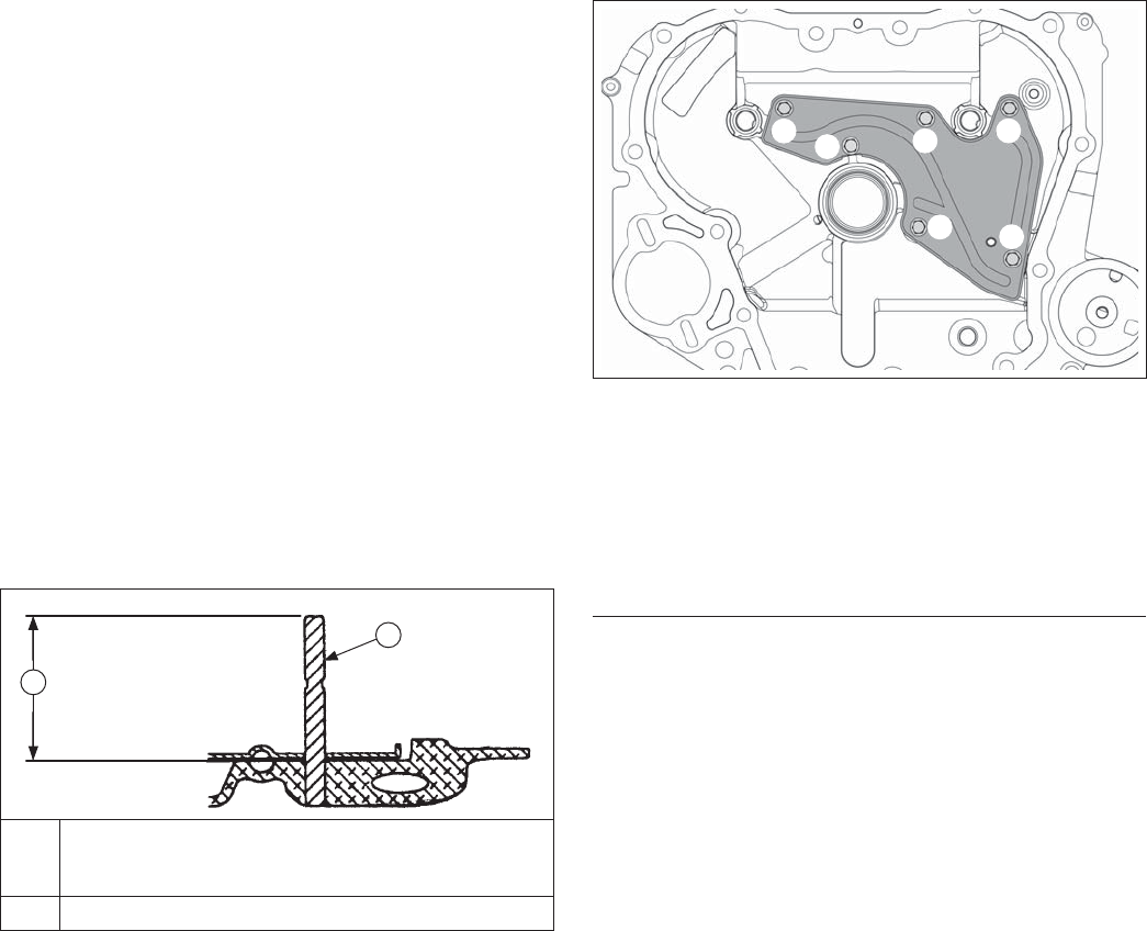
Install Governor Shaft
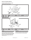
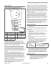
Governor Shaft Components and Details
A
B
A
44.50 mm (1.750 in.) To Gasket Surface - Before
Oil Passage Cover Plate and Gasket are
Assembled
B Governor Gear Shaft
1. Install new pin by pressing or lightly tapping it into
closure plate. It must be installed so that it protrudes
44.50 mm (1.750 in.), plus or minus 0.101 mm
(0.004 in.) above crankcase boss.
2. Install new governor regulating pin and governor
gear assembly.
3. Make sure governor gear assembly rotates freely.
4. Check that timing marks are still aligned.
5. Install a new closure plate gasket and install closure
plate. Torque fasteners to 24.5 N·m (216 in. lb.).
6. Complete engine reassembly following Reassembly
procedures.
7. When engine reassembly is completed, reset initial
governor adjustment according to procedure in
Governor System.
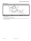
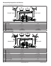
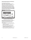
Closure Plate and Passage Cover Inspection and
Service
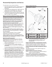
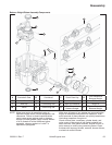
Passage Cover Torque Sequence
6
1
5
2
3
4
If disassembly was performed, inspect and ensure
oil passages in closure plate and passage cover are
completely clean and not obstructed in any way. Check
straightness of passage cover if required, against a fl at
surface.
Use a new passage cover gasket and install passage
cover onto closure plate. Reinstall mounting screws and
torque to 4.0 N·m (35 in. lb.), following sequence.
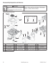
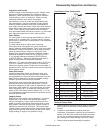
Remove Cam Gears, Cam Shafts, and Oil Pump
NOTE: ACR weight and spring normally captured by
thrust washer and installation of closure plate,
will fall out if exhaust cam gear is turned upside
down.
NOTE: Cam gear assemblies may contain either two or
four rivets.
NOTE: Engine Serial No. 332740003 and lower, use a
rubber outlet between oil pump outlet and lower
bearing area. Some models use an open seal
with an internal passage to feed oil to lower
bearing. Some models use a closed or solid
seal, and crankshaft is crossed-drilled to feed oil
to lower bearing.
Engine Serial No. 332740003 and higher, outlet
of oil pump is closed and no rubber seal is used.