


60
Disassembly/Inspection and Service
KohlerEngines.com 20 690 01 Rev. F
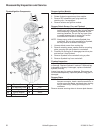
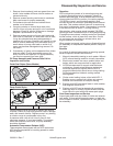
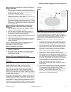
To install piston rings, proceed as follows:
1. Oil control ring (bottom groove): Install expander and
then rails. Make sure ends of expander are not
overlapped.
2. Compression ring (center groove): Install center ring
using a piston ring installation tool. Make sure
identifi cation mark is up when ring is installed.
3. Compression ring (top groove): Install top ring using
a piston ring installation tool. Make sure identifi cation
mark is up when ring is installed.
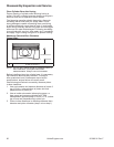
Remove Crankshaft and Balance Weight Assembly
Carefully remove crankshaft and balance weight
assembly from crankcase. On engines with Second
Generation Balance Weight, carefully lift lower control
link (for balance weight), off boss of crankcase as
crankshaft is removed. Models with Third Generation
Balance Weight have a balance weight guidance
shaft and link which can be removed before removing
crankshaft and balance weight assembly.
Crankshaft and Crank Gear Inspection and Service
Inspect teeth of crank gear. If teeth are badly worn,
chipped, or some are missing, replacement of crank
gear will be necessary. Remove gear by pulling it off key
and crankshaft.
Inspect crankshaft bearing journal surfaces for wear,
scoring, grooving, etc. If they show signs of damage or
are out of running clearance specifi cations, crankshaft
must be replaced.
Inspect crankshaft keyways. If worn or chipped,
replacement of crankshaft will be necessary.
Inspect crankpin for wear, score marks or aluminum
transfer. Slight score marks can be cleaned with crocus
cloth soaked in oil. If wear limits are exceeded, it will be
necessary to replace crankshaft.
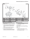
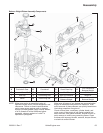
Balance Weight Disassembly
If necessary, First and Second Generation Balance
Weight Assembly can be separated from crankshaft.
Disassemble only if required.
1. Remove crank gear from crankshaft and carefully
remove key from keyway.
2. For fi rst generation balance weight assembly:
remove guide shoe from guide pin on fl ywheel side
of assembly.
For second generation balance weight assembly:
remove link from guide pin on PTO side of assembly.
3. Remove long hex fl ange screw securing two balance
weight halves together on crankshaft. Note
orientation of all parts. Guide pin is on fl ywheel side
for balance weight design with closure plate side
guide shoe. Guide pin is on PTO side for balance
weight design with lower control link. Hold guide pin
with wrench or torx bit socket as required. Do not
hold or damage outside diameter (O.D.) of guide pin.
4. Mark weights for proper reassembly and carefully
slide balance weights off crankshaft eccentrics.
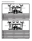
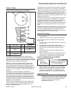
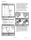
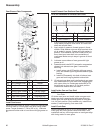
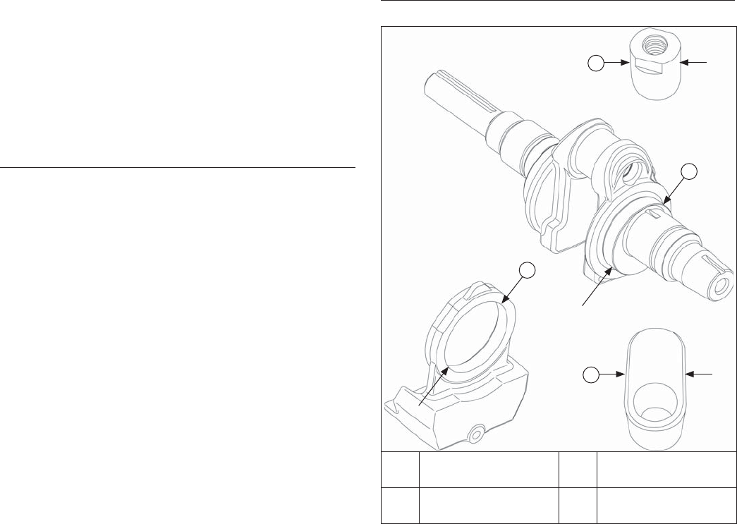
Balance Weight Assembly
Measurement Locations
C
B
A
D
A Guide Pin O.D. B
Crankshaft
Eccentric
C
Balance Weight
Bearing Surface
D
Balance Weight
Guide Shoe
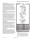
NOTE: These procedures apply only to First and
Second Generation Balance Weights. Third
Generation Balance Weight should not be
disassembled.
Balance weight assembly counterbalances crankshaft
weights and internal forces during operation to minimize
vibration. Several key areas of balance weight must
be checked before installation and use. Additionally,
mating components (crankshaft eccentrics and closure
plate guide channel) must also be inspected for wear or
damage.
Use these procedures to check balance weight and
matching components.
Balance Weight-to-Eccentric Clearance
NOTE: Do not use a feeler gauge to measure balance
weight-to-eccentric clearance.
Before balance weight assembly is reassembled to
crankshaft, running clearance to crankshaft eccentrics
must be accurately checked. Failure to maintain required
clearances will result in vibration or engine failure.