


65
Reassembly
20 690 01 Rev. F KohlerEngines.com
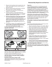
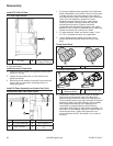
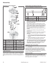
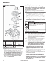
5. Install intake cam shaft down into crankcase boss.
Seat rubber oil pump outlet seal into machined
pocket. If an open style outlet seal is used, check to
make sure small feed hole is open and aligned with
lower main bearing oil feed hole. Use a 3/32” allen
wrench, or a light with a mirror. Push steel sleeves in
pump housing down until bottomed against mounting
surface. Install two M5 mounting screws. Hold pump
outlet against main bearing area and torque screws
to 6.2 N·m (55 in. lb.) into new holes, or 4.0 N·m (35
in. lb.) into used holes.
6. If engine uses a drain back tube, insert round
fl anged end into hole near base of cylinder and clip it
onto oil pump body.
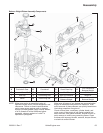
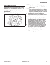
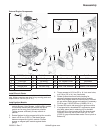
Install Crankshaft and Balance Weight
NOTE: If installing a crankshaft with third generation
balance weight, steps 1 and 2 do not need to be
performed.
1. Assemble crankshaft balance weight if removed
from crankshaft.
a. Lubricate crankshaft eccentrics and balance
weight bearing surfaces with oil.
b. Install two balance weight halves onto crankshaft
eccentrics as marked or originally installed.
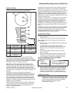
c. First generation balance weight assembly: Align
weights and install balance weight screw, through
mounting holes, from PTO side. Thread it into
guide pin outside weight on fl ywheel side. Hold
guide pin with a wrench or Torx bit, and torque
screw to 11.3 N·m (100 in. lb.). Do not hold, or
damage outside diameter (O.D.) of guide pin.
Second generation balance weight assembly:
Align weights and insert balance weight screw,
through mounting holes from fl ywheel side.
Thread it into guide pin outside weight on PTO
side. Hold guide pin with a wrench or Torx bit, and
torque screw to 11.3 N·m (100 in. lb.). Do not
hold, or damage outside diameter (O.D.) of guide
pin. Apply grease to inner diameter (I.D.) of each
hole in control link and install one end over guide
pin.
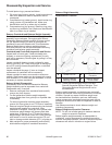
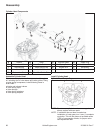
2. Carefully install crank gear key in keyway.
3. First generation balance weight assembly: Carefully
install crankshaft into crankcase, through PTO seal,
and seat fully into place. Rotate crankshaft so
journal for connecting rod is away from cylinder.
Second generation balance weight assembly: Make
sure pivot pin on boss in lower section of crankcase
is clean and free of any nicks, or surface
irregularities. Apply a small amount of grease to O.D.
Third generation balance weight assembly: Carefully
install crankshaft into crankcase, through PTO seal,
and seat fully into place.
4. First generation balance weight assembly: Install
balance weight guide shoe onto guide pin with solid
end toward crankshaft.
Second generation balance weight assembly: Apply
a small amount of grease to O.D. of guide pin on
PTO side of counterweight and install control link.
Carefully install crankshaft with link (hold in position
as required), through PTO seal. Slightly rotate
counterweight assembly and guide outer end of link
over stationary guide pin in crankcase. Seat link and
crankshaft fully into place, do not force either part
into position.
Third generation balance weight assembly: Apply a
small amount of engine oil to ends of guidance shaft.
Install guidance shaft through links into boss of
crankcase.
Install Piston Rings
NOTE: For detailed piston inspection procedures and
piston ring installation refer to Disassembly/
Inspection and Reconditioning.
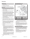
Install Piston to Connecting Rod
Assemble piston, connecting rod, piston pin, and piston
pin retainers.
Install Piston and Connecting Rod
NOTE: Proper orientation of piston/connecting rod
inside engine is extremely important. Improper
orientation can cause extensive wear or
damage.
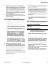
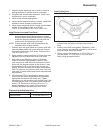
1. Stagger piston rings in grooves until end gaps are
120° apart. Lubricate cylinder bore, crankshaft
journal, connecting rod journal, piston, and rings with
engine oil.
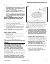
2. Compress piston rings using a piston ring
compressor. Orient FLY mark on piston toward
fl ywheel side of crankcase. Place ring compressor
on top surface of crankcase and make certain it is
seated down around entire circumference. Use a
soft, rubber grip hammer handle and tap piston/
connecting rod into bore. First tap should be rather
fi rm, so oil ring moves from compressor into bore in
one smooth, quick motion. Otherwise oil ring rails
may spring out and jam between ring compressor
and top of bore.
3. Guide connecting rod down and rotate crankshaft to
mate journals. Install rod cap.
4. Install screws and torque in 2 increments, fi rst to
5.5 N·m (50 in. lb.), fi nally to 11.5 N·m (100 in. lb.).