


37
Electrical System
20 690 01 Rev. F KohlerEngines.com
Electronic Ignition System Tests
NOTE: Ignition tester must be used to test ignition on these engines. Use of any other tester can result in inaccurate
fi ndings. Battery on unit must be fully charged and properly connected before performing tests (a battery that
is hooked up or charged backward will crank engine but it won’t have spark). Be certain drive is in neutral and
all external loads are disconnected.
Test Ignition Systems
NOTE: If engine starts or runs during testing, you may need to ground kill lead to shut it down. Because you have
interrupted kill circuit, it may not stop using switch.
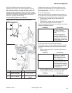
Isolate and verify trouble is within engine.
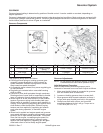
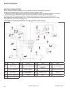
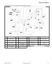
1. Locate connectors where wiring harnesses from engine and equipment are joined. Separate connectors and
remove white kill lead from engine connector. Rejoin connectors and position or insulate kill lead terminal so it
cannot touch ground. Try to start engine to verify whether reported problem is still present.
Condition Possible Cause Conclusion
Problem goes away. Electrical System Check key switch, wires, connections,
safety interlocks, etc.
Problem persists. Ignition or Electrical System Leave kill lead isolated until all testing
is completed.
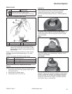
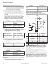
Test for Spark
NOTE: To maintain engine speeds normally obtained during cranking, do not remove engine spark plug.
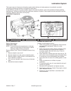
1. Make sure spark plug lead is connected to spark plug.
2. Check condition of spark plug. Make sure gap is set to 0.76 mm (0.030 in.). If plug is in good condition, check/
adjust gap and reinstall.
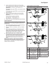
3. a. Test for spark with ignition tester. Disconnect spark plug lead and connect it to post terminal of tester. Connect
clip to a good ground, not spark plug.
b. Make sure engine ignition switch, kill switch, or key switch is in RUN position.
4. Crank engine (minimum speed 500 RPM), and observe tester. Visible and audible sparks should be produced.
Condition Possible Cause Conclusion
Audible and visible sparks are
produced.
Ignition Module
Ignition module is OK.
Audible and visible sparks are not
produced.
Ignition Module or Electrical System Make sure engine ignition switch,
kill switch, or key switch is in RUN
position.
Check wires and terminals of ignition
module and other components for
accidental grounding and damaged
insulation.
If wires and terminals are OK, ignition
module is probably faulty and should
be replaced. Test module further using
an ohmmeter.
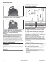
Test Ignition Module with Ohmmeter
NOTE: This test cannot be performed unless module has been fi red at least once.
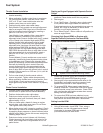
Measure resistance of module secondary using an ohmmeter.
1. Zero ohmmeter.
2. Connect one ohmmeter lead to laminations. Connect other lead to spark plug terminal of high-tension lead.
3. With ohmmeter leads connected in this manner, resistance of secondary should be 7,900 to 18,400 ohms. Refer
to Disassembly and Reassembly for complete ignition module removal and installation procedures.
Condition Possible Cause Conclusion
Resistance is within specifi ed range. Module Secondary Module secondary is OK.
Resistance is low or 0 ohms. Module secondary is shorted.
Replace module.
Resistance is high or infi nity ohms. Module secondary is open. Replace
module.