55
APPENDIX A
Installation
Installation
The GPS 120 XL must be properly installed accord-
ing to the following instructions to get the best possible
performance.
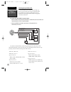
To complete the standard installation, you will need
the following pieces:
• 1 amp in-line fuse (may be included with
Power/Datacable)
• Four 1/4” (6mm) diameter mounting screws
• 1” x 14 marine antenna mount and screws
Several optional accessories are also available to
provide flexible installation on any vessel. See your
GARMIN dealer for more information on these items:
• AC Adapter
• Antenna Cable Extension
• Cigarette Lighter Adapter
To begin installation, you’ll need to select a suitable
mounting position for the antenna and the unit. Once
you’ve identified the best mounting location, install the
antenna and cable first, then the unit and wiring
harness.
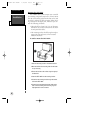
Mounting the GPS antenna
The antenna should be mounted in a location that
has a clear, unobstructed view of the sky in all direc-
tions to ensure the best reception in all conditions.
Avoid mounting the antenna where it will be shaded by
the boat’s superstructure, a radome antenna, or mast.
Most marine VHF and loran antennas will not seriously
degrade the GPS antenna’s reception. Never paint the
antenna or clean it with harsh solvents.
To install the GPS antenna:
1. Screw the antenna directly onto the 1” – 14 mount.
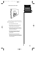
2. Route the cable to the location of the display unit, using
the appropriate tie-wraps,escutcheon plates and sealant
to secure the cable along the route and through any
bulkhead or deck.
3. Once the GPS 120XL unit has been installed, connect the
cable to the antenna connector on the back of the dis-
play unit. Turn the antenna connector 1/4 turn clockwise
to lock the cable into place.
120XL Man RevB 7/10/98 10:55 AM Page 55


