


190-00067-25 Rev D 1-3
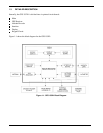
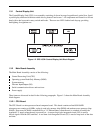
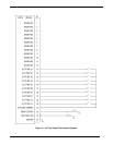
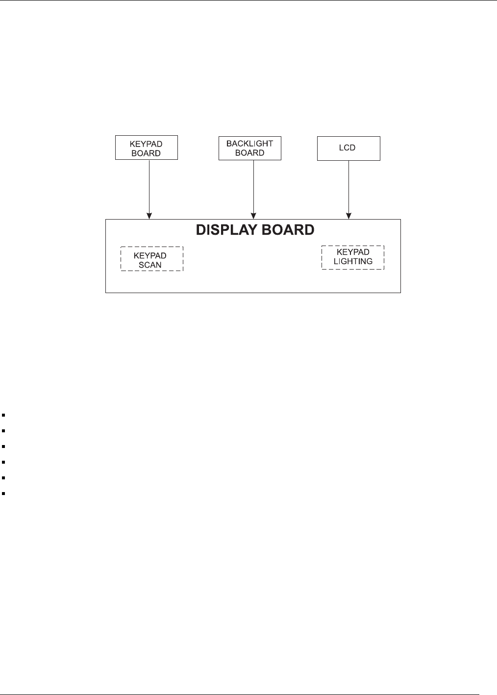
1.3.1 Control Display Unit
The Control/Display Unit (CDU) is an assembly consisting of eleven keycaps, keypad board, optical lens, liquid
crystal display and board with heat sealed drivers, photocell and screws. All components are housed in a die cast
bezel with a dual concentric rotary switch and knobs. There are two LED’s behind each keycap, providing
backlighting for nighttime use.
Figure 1-2. GPS 155XL Control/Display Unit Block Diagram
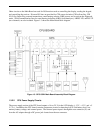
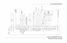
1.3.2 Main Board Assembly
The Main Board Assembly consists of the following:
Central Processing Unit (CPU)
Operating system Read-Only Memory (ROM)
System memory
Discrete Input/Output (I/O)
Serial communication drivers and receivers
Power supply
These items are discussed in detail in the following paragraphs. Figure 1-3 shows the Main Board Assembly
block diagram.
1.3.2.1 CPU Board
The CPU Board is a microprocessor-based computer board. This board contains an Intel 80L186EB
microprocessor running at 16 MHz, a plug-in read only memory chip (ROM) and random access memory chips
(RAM). Data stored in RAM is maintained by a 3-V lithium battery when the unit is switched off and by the
regulated 5-V supply when the unit is powered on. A custom large scale integrated circuit (LSI) is used to
decode signals from the GPS satellites. A real time clock Integrated Circuit (IC) is used to keep track of the date
and time.