


190-00067-25 Rev D 1-1
SECTION 1
DESCRIPTION AND OPERATION
1.1 INTRODUCTION
This manual provides assembly-level repair information for the GARMIN GPS 155XL. If necessary, the GPS
155XL can be returned to GARMIN for all service work. Contact GARMIN at the following address for further
service information:
GARMIN
1200 E. 151st Street
Olathe, KS 66062 USA
Telephone: 913-397-8200
Dealer Line: 1-800-800-1420
Website Address: www.garmin.com
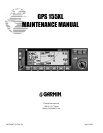
1.2 GENERAL DESCRIPTION
The GPS 155XL is an aircraft rack-mounted GPS receiver that meets TSO-C129a (Al) requirements for
Instrument Flight Rules (IFR) enroute, terminal, and non-precision approach operations. The unit features a 12
parallel-channel receiver for tracking up to twelve satellites simultaneously. The GPS 155XL provides Course
Deviation Indication (CDI) on an 80 x 240 double supertwisted nematic (DSTN) display. The display also
features automatic contrast adjustment with reverse mode. An optional, remote-mounted recharging battery is
available which provides up to two hours of navigation (with screen time-out enabled) in the event of an aircraft
electrical system failure.
The unit is constructed from high-quality materials and uses the latest techniques in manufacturing technology.
In order to achieve the desired reliability, size and power requirements, surface mount components are used
extensively. Specialized equipment and procedures are required to repair circuit boards using surface-mount
components. GARMIN does not authorize the repair of GPS 155XL circuit boards. All circuit boards and
assemblies for the GPS 155XL can be affordably replaced through the GARMIN board exchange program, if
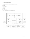
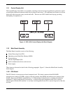
necessary. The following assemblies and printed circuit boards are field replaceable:
Altitude Decoder Board—Printed circuit board which contains the altitude decoder circuits and interface
circuitry.
Display Board Assembly—Contains the LCD, backlight and display circuit boards.
Rotary Switch Assembly—Contains dual concentric switch and its assembled wiring harness.
Control/Display Unit—Contains bezel, buttons, lens, keypad board, light pipes, front insert, plus the LCD
display assembly and rotary switch assembly.
Main Board—Printed circuit board which contains the microprocessor, LSI, and power supply circuitry.
GPS Receiver Assembly—A module containing the GPS receiver and high precision crystal oscillator.
Interface Board—Printed circuit board that connects the Main Board to the front loading NavData® card.
External Battery Pack—A module containing rechargeable cells, fuse and charging circuits.