


190-00067-25 Rev D 5-3
5.4 TESTING
5.4.1 Test Setup
1. Before connecting a test harness to the unit, set the power supply to +13.8 VDC ±0.1 V at J1-25, and set
current limiter to 3A.
2. Turn power supply OFF.
3. Connect a test harness (figures 2-1 and 2-2) to the unit and turn the power supply ON.
5.4.2 Test Procedure
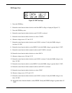
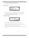
Test Mode Activation/Display Test
1. Enter the test mode by holding down the ENT key and rotating the Power Knob clockwise. The unit
should display four test patterns. The first pattern turns on all pixels and shows a light background.
The second pattern turns off all pixels and shows a dark background. The third pattern turns on
every other pixel and shows a checkerboard pattern. The fourth pattern turns on every third pixel and
shows a diagonal stripe pattern.
2. Observe the test patterns and verify the display and backlighting are working properly.
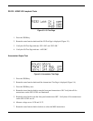
CDI Deflection Test
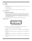
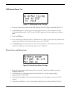
Figure 5-1. CDI Deflection Test Page
1. Rotate the outer function knob clockwise until the CDI Test Page is displayed (Figure 5-1).
2. Measure voltage across J1-1 and J1-4. Press the CRSR key once.
3. If necessary, rotate the inner function knob to select CENTERED. Verify the DMM voltage is
0 ±15 mV.
4. Rotate the inner function knob clockwise to select FULL RIGHT. Verify the DMM voltage is
-150 ±15 mV.
5. Rotate the inner function knob clockwise to select MAX RIGHT. Verify the DMM voltage is
-300 ±30 mV.
6. Rotate the inner function knob clockwise to select MAX LEFT. Verify the DMM voltage is
+300 ±30 mV.