


1-6 190-00067-25 Rev D
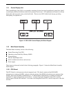
1.3.4 Interface Board and Data Cards
When servicing the GPS 155XL, user-defined waypoints, routes, settings, etc.,
may be saved on a user data card (768 kilobytes of Flash Memory; P/N 010-
10032-03). Refer to the GPS 155XL Pilot’s Guide for additional information on
using the data card.
The Interface Board provides two-way data transfer capability between the CPU board and a Data Card. Address
and data lines from the CPU board route through the Interface Board to the data card. A plastic race secures the
Interface Board at the front of the unit and serves to guide the data card onto a 40-pin connector.
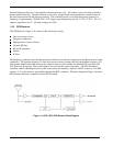
1.3.5 Altitude Decoder Board
The Altitude Decoder Board contains the 26-pin rear connector (J2), discrete/parallel inputs and
Gillham/Greycode decoder circuitry. Encoded pressure altitude data from a parallel altimeter device is received
as a 10-bit data word at the 26-pin rear connector. Diode isolation on these input lines prevents damage to the
unit. The data is then decoded and output to the Main Board. The Altitude Decoder Board also provides a
discrete input for the GPS SEQ switch. When grounded, this line activates the unit’s HOLD mode.