


4-2 190-00067-25 Rev D
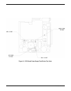
4.3.2 Control/Display Unit (Figure 7-1)
1. Remove Covers (paragraph 4.3.1).
2. Remove power control knob and shaft (5) by loosening Set Screw (6) on the coupling sleeve. Retain
the Shoulder Washer (7).
3. Remove four Flathead screws (8), which attach the CDU to the chassis.
4. Carefully remove the CDU from the chassis, pulling the assembly away from the two CPU board
connectors and the power switch.
4.3.3 Removing the Altitude Decoder Chassis Subassembly (Figure 7-1)
1. Remove the Covers as described in paragraph 4.3.1.
2. Remove the two Screws (9), which connect the Casting (10) to the GPS Receiver.
3. Slightly loosen Screw (11). The Main Assembly can now be hinged opened by lifting up on the
Casting (10) while holding the Main Assembly down. This allows troubleshooting the CPU Board
without completely removing the Altitude Decoder Subassembly.
4. Remove Screw (11) and completely remove the Altitude Decoder Chassis.
5. Remove the Ribbon Cable from the J13 Connector on the Altitude Decoder and the J8 Connector on
the CPU Board.
6. Remove the Altitude Decoder Board Chassis by sliding rearward approximately ¼” until the hinge
slips out of the hole in the Main Chassis.
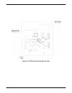
4.3.4 Interface Board Removal (Figure 7-3)
1. Remove the Covers as described in paragraph 4.3.1.
2. Remove the CDU as described in paragraph 4.3.2.
3. Remove the Altitude Decoder Subassembly as described in paragraph 4.3.3.
4. Remove the Side Casting (12) by removing the three Screws (13) and pull the casting up and out as a
unit.
5. Remove the three flat head Screws (9) retaining the Data Card Race (10) and the Interface Board
(11).
6. Slip the Data Card Race (10) off the Interface Board Connector (11).
7. Carefully pull the Interface Board out of the unit upward, disengaging it from the CPU Board
Connector.