


1-4 190-00067-25 Rev D
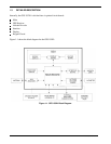
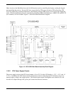
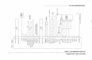
Other circuits on the Main Board are used for I/O functions such as controlling the display, reading the keypad,
and controlling the receiver. Discrete I/O lines are provided for CDI course deviation, CDI to/from flag, CDI
NAV flag, Super Flag, external annunciators, omni bearing selector (OBS) course, and to activate the Approach
mode. Serial communication lines for omni bearing indication (OBI) (clock/data/sync), ARINC 429, and RS-232
(two channels) are also included. Figure 1-3 shows the Main Board block diagram.
Figure 1-3. GPS 155XL Main Board Assembly Block Diagram
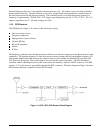
1.3.2.2 CPU Power Supply Circuits
The power supply section of the CPU board outputs +14 to +29 V for the LCD display, ± 12 V, + 15 V, and +5
V (V
CC
). In addition, the CPU board contains comparator circuits for detecting low Ni-Cad battery level, low
memory battery voltage, and external power. The external power input is through the rear connector (J1) and
from the AC adapter through a DC power jack located near the rear connector.