


190-00067-25 Rev D 3-3
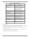
3.4 INITIAL TROUBLESHOOTING
Remove the NavData card before disassembling the unit.
The first step in troubleshooting the GPS 155XL is to remove the top and bottom covers (see paragraph 4.3.1).
Next, verify the unit is being properly powered and the internal clock is functional.
3.4.1 Power Supply Check
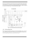
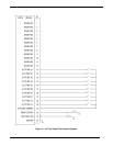
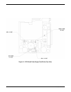
1. Check the DC voltage between D511 and ground as shown in Figure 3-1. The voltage should read
between -9.60 and -14.40 V. If the voltage is out of the limits specified, replace the CPU board.
2. Check the DC voltage between L502 and ground as shown in Figure 3-1. The voltage should read
between 4.8 and 5.2 V. If the voltage is out of the limits specified, replace the CPU board.
3. Check the voltage between L504 and ground as shown in Figure 3-1. The voltage should read
between 9.6 and 14.4 V. If the voltage is out of the specified limits replace the CPU board.
4. Check the DC voltage between Q511 and ground as shown in Figure 3-1. The voltage should read
between 14 and 29 V. If the voltage is out of the specified limits replace the CPU board.
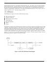
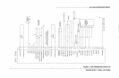
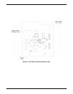
5. Check the DC voltage between D508 and ground as shown in Figure 3-2. The voltage should read
between 12 and 18 V. If the voltage is out of the specified limits replace the CPU board.
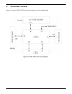
3.4.2 Internal Clock Check
Check the clock speed by placing an oscilloscope probe at I101, pin 28 as shown in Figure 3-2. The frequency
should be approximately 32 MHz. If the clock is not operational, replace the GPS receiver. If the clock still fails
to function, replace the CPU Board.