


190-00067-25 Rev D 4-3
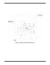
4.3.5 CPU Board Removal (Figure 7-3)
1. Remove covers as described in paragraph 4.3.1.
2. Remove CDU as described in paragraph 4.3.2.
3. Remove Interface Chassis Subassembly as described in paragraph 4.3.3.
4. Remove screw (1), shoulder washer (2), and insulator (3) holding the I501 Regulator to the main
chassis.
5. Carefully turn the unit over.
6. The power/volume switch uses a flexible circuit cable for connection to the CPU board. This
flexible circuit cable is inserted into a ZIF connector (J11). Pull up on the retaining lip of the ZIF
connector and gently pull the flexible circuit cable from the connector.
7. Remove bottom shield cover from CPU Board and disconnect GPS receiver cable from connector J6.
8. Remove two flat head screws (4), which hold 37-pin DSUB connector to the main chassis.
9. Remove two screws (5) that hold CPU Board to the main chassis.
10. Carefully pull up on the CPU Board, away from the power switch.
4.3.6 GPS Receiver Assembly Removal and Disassembly (Figures 7-2, & 7-3)
1. Remove covers as described in paragraph 4.3.1.
2. Partially remove Altitude Decoder Chassis Subassembly as described in paragraph 4.3.3.
3. Remove bottom shield cover from CPU Board and disconnect GPS receiver cable from connector J6.
4. For steps 4 and 5, refer to Figure 7-3. Remove screw (1), shoulder washer (2), and insulator (3)
holding I501 Regulator to main chassis.
5. Remove screw (14), and remove GPS Receiver Assembly from main chassis.
6. For steps 6-13, refer to Figure 7-2. Remove eleven screws (1) that secure GPS receiver outer cover
to casting.
7. Remove four screws (2) holding GPS receiver inner cover to assembly. Lift screws out along with
spacers (3).
8. Remove inner cover from assembly. Gently pry cover out if necessary.
9. Remove cable from connector J101.
10. Remove plastic screw (4) holding PC board to casting.