


5-4 190-00067-25 Rev D
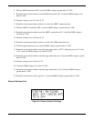
7. Rotate the inner function knob clockwise to select FULL LEFT. Verify the DMM voltage is
+150 ±15 mV.
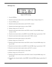
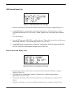
CDI To/From Flag Test
1. Rotate the outer function knob clockwise.
2. Measure voltage across J1-2 and J1-4.
3. If necessary, rotate the inner function knob to select FLAG. Verify the DMM voltage is 0 ±15 mV.
4. Rotate the inner function knob clockwise to select FROM. Verify the DMM voltage is -83 ±20 mV.
Note: If the unit is equipped with Mod Status 1, the FROM voltage should be -190 ±40 mV at full-
scale deflection. The TO voltage should be +190 ±40 mV at full-scale deflection.
5. Rotate the inner function knob clockwise to select TO. Verify the DMM voltage is +83 ±20 mV.
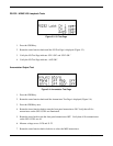
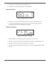
CDI Nav Flag Test
1. Rotate the outer function knob clockwise.
2. Measure voltage across J1-3 and J1-4.
3. If necessary, rotate the inner function knob to select IN VIEW. Verify the DMM voltage is 0 ±25
mV.
4. Rotate the inner function knob clockwise to select OUT OF VIEW. Verify the DMM voltage is 375
±80 mV.
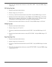
Super Flag Output Test
1. Rotate the outer function knob clockwise.
2. Measure voltage across J1-10 and J1-22.
3. If necessary, rotate the inner function knob to select IN VIEW. Verify the DMM voltage is less than
250 mV.
4. Rotate the inner function knob clockwise to select OUT OF VIEW. Verify the DMM voltage
is greater than 12.8 V.