Especially in inclement weather, longer-range radar signals
can increase the clutter on the Radar screen and make it
more difficult to view information about shorter-range targets.
In rain, shorter-range radar signals can enable you to view
information about nearby objects more effectively, if the rain
clutter setting is configured optimally.
• Select the shortest effective range, given your reason for
using radar and the present environmental conditions.
Adjusting the Zoom Scale on the Radar
Screen
The radar zoom scale, also called the radar signal range,
represents the distance from your position (the center) to the
outermost ring.
From a Radar screen, select or .
Each ring represents an even division of the zoom scale.
For example, if the zoom scale is set at 3 miles, each ring
represents 1 mile from the center out.
Sentry Mode
Sentry mode allows you to put the radar into timed-transmit
mode, in which you can configure a radar transmit and standby
cycle to conserve power. You can also enable a guard zone in
this mode, which identifies a safe zone around your boat and
sounds an alarm when a radar object enters the zone. Sentry
mode works with all Garmin GMR model radars.
Enabling Timed Transmit
From the sentry screen, select MENU > Sentry Setup >
Timed Transmit > On.
Setting the Standby and Transmit Times
Before you can set the standby and transmit times, you must
enable timed transmit (Enabling Timed Transmit).
To help conserve power, you can indicate the radar standby
time and the transmit time to implement periodic radar signal
transmissions at set intervals.
1
From the sentry screen, select MENU > Sentry Setup.
2
Select Stdby Time.
3
Enter the time interval between radar signal transmissions.
4
Select Transmit Time.
5
Enter the duration of each radar signal transmission.
Enabling a Guard Zone
From the sentry screen, select MENU > Sentry Setup >
Enable Guard Zone.
Defining a Circular Guard Zone
Before you can define the boundaries of the guard zone, you
must enable a guard zone (Enabling a Guard Zone).
You can define a circular guard zone that completely
encompasses your boat.
1
From the sentry screen, select MENU > Sentry Setup >
Adjust Guard Zone > Move Radar Guard Zone > Circle.
2
Select the location of the outer guard zone circle.
3
Select the location of the inner guard zone circle to define
the width of the guard zone.
Defining a Partial Guard Zone
You can define the boundaries of a guard zone that does not
completely encompass your boat.
1
From the sentry screen, select MENU > Sentry Setup >
Adjust Guard Zone > Move Radar Guard Zone > Corner
1.
2
Touch and drag the location of the outer guard-zone corner
À
.
3
Select Corner 2.
4
Touch the location of the inner guard-zone corner
Á
to
define the width of the guard zone.
Marking a Waypoint on the Radar Screen
1
From a Radar screen or the Radar overlay, select a location.
2
Select New Waypoint.
Viewing a List of AIS Threats
From any Radar screen or the Radar overlay, you can view and
customize the appearance of a list of AIS threats.
From a Radar screen or the Radar overlay, select MENU >
Other Vessels > AIS/MARPA List.
Showing AIS Vessels on the Radar Screen
AIS requires the use of an external AIS device and active
transponder signals from other vessels.
You can configure how other vessels appear on the Radar
screen. If any setting (except the AIS display range) is
configured for one radar mode, the setting is applied to every
other radar mode. The details and projected heading settings
configured for one radar mode are applied to every other radar
mode and to the Radar overlay.
1
From a Radar screen or the Radar overlay, select MENU >
Other Vessels > AIS/MARPA Dis. Setup.
2
Select an option:
• To indicate the distance from your location within which
AIS vessels appear, select AIS Dis. Range, and select a
distance.
• To show details about AIS-activated vessels, select
Details > Show.
• To set the projected heading time for AIS-activated
vessels, select Projected Heading, and enter the time.
• To show the tracks of AIS vessels, select Trails, and
select the length of the track that appears.
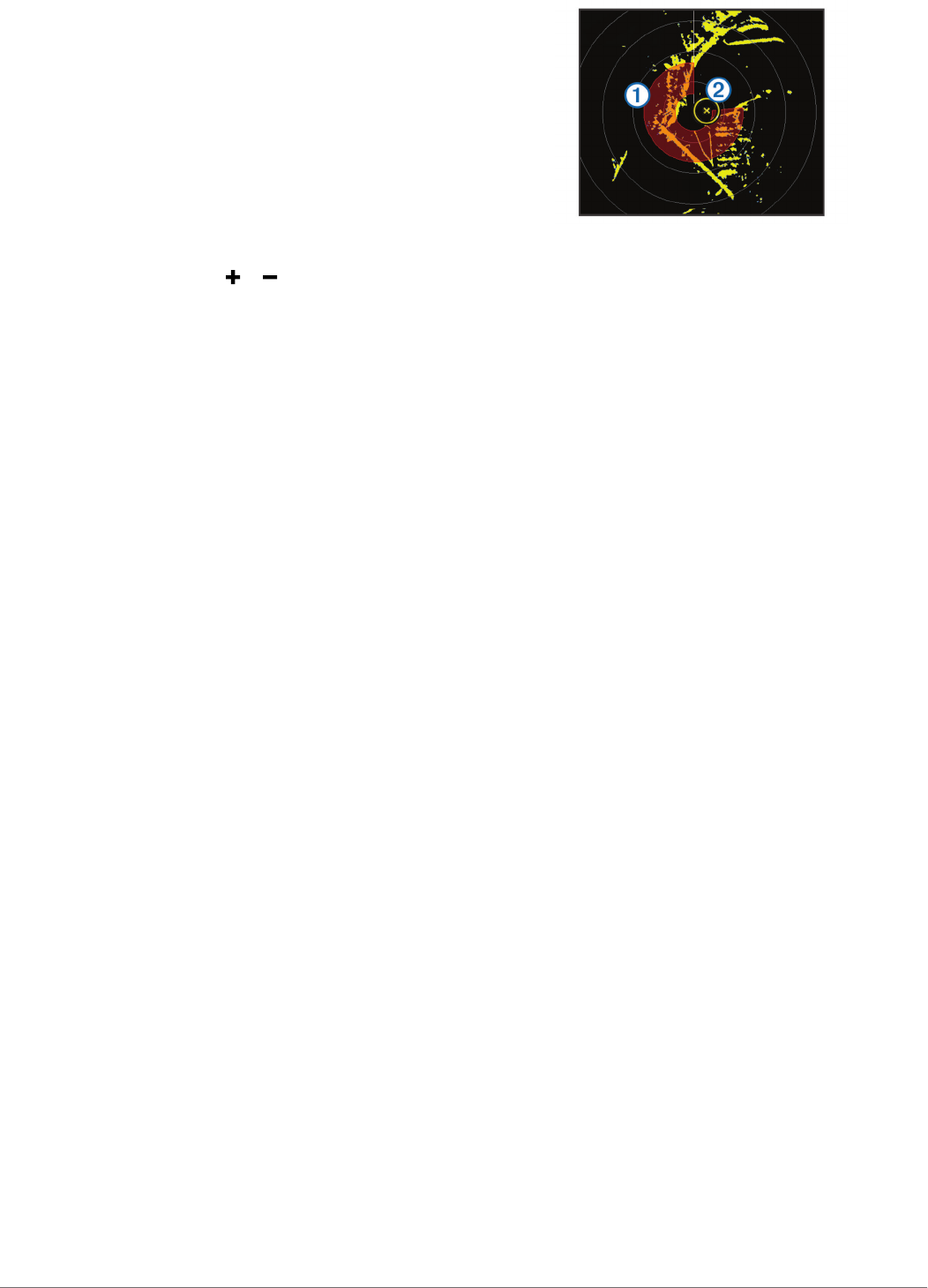
VRM and EBL
The variable range marker (VRM) and the electronic bearing
line (EBL) measure the distance and bearing from your boat to
a target object. On the Radar screen, the VRM appears as a
circle that is centered on the present location of your boat, and
the EBL appears as a line that begins at the present location of
your boat and intersects the VRM. The point of intersection is
the target of the VRM and the EBL.
Showing the VRM and the EBL
The VRM and the EBL configured for one mode are applied to
other radar modes.
NOTE: The VRM and the EBL cannot be changed in sentry
mode.
From a Radar screen, select MENU > Show VRM/EBL.
Adjusting the VRM and the EBL
Before you can adjust the VRM and the EBL, you must show
them on the Radar screen (Showing the VRM and the EBL).
18 Radar


