


AP-8
4. On the "TCPA Set" line, select a TCPA limit
desired. (30s, 1, 2, 3, 4, 5, 6, 12M)
5. Press the [ACQ/ENTER] key.
6. Press the [MENU] key to close the menu.
The flashing of the triangle plot symbol and
vector remain on the screen until the danger-
ous situation is no longer present or you in-
tentionally terminate tracking of the target by
using the [SELECT/CANCEL] key.
Lost Target Alarm
When the system detects a loss of a tracked
target, the target symbol becomes a flashing
diamond.
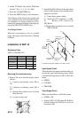
Installation of ARP-10
Necessary Parts
ARP-10 (000-086-852)
emaNepyT.oNedoCytQ
draoB01-PRA
7009P81039-674-800
1
recapS
02-QS056-108-000
3
rehsaWgnirpS
W1915C3M402-468-000
3
wercSdaeHnaP
W0072C8x3M404-188-000
3
wercSdaeHnaP
*)rehsaw/w(
01MRWS8x3477-508-0003
* Not used.
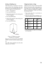
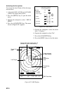
Mounting (For technician only)
1. Remove the cover from the display unit as
follows.
1 Unscrew four binding screws (M4 x
10).
2 Unfasten six binding screws (M3 x
10).
3 Remove three rubber covers to loosen
three hex nuts.
4 Loosen two hex nuts.
1
1
1
1
2
2
3
4
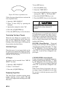
2. Attach the ARP-10 Board to the right-hand
chassis of the display unit, using the spacer
supplied as follows.
1) Fasten three spacers tightly.
2) Attach the P107 connector on ARP-
10 Board to J107 connector on
SPU Board.
3) Tighten three pan head screws to fix the
ARP-10 Board.
$
$
Spacer
SQ-20 3pcs.
Spring Washer
M3 3pcs.
Pan Head
Screw
M3 x 8 3pcs.
J107
P107
SPU Board
SPU9211
ARP-10 Board
18P9007
Front
$: Pull the front panel slightly to fix these screws.
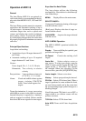
Input Signal Check
Place the radar in transmit condition after con-
necting the speed and heading sensor. Make
sure the following items are OK on Self Test
menu.
• SPEED
• COURSE
• TRIGGER
Video Signal Check
Make sure the follows on Self Test menu.
• VIDEO : OK
• Adjust GAIN, A/C SEA and A/C RAIN so
that the readout for FE-DATA 1 and 2 are
less than 1,000.