


33
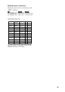
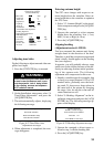
¡. Nav Talker
2 . Depth Unit
3 . Temp Unit
4 . Hdg Sensor
5 . Key Beep
6 . Ant on Tx
7 . Dead Sector
8 . Tuned/Video
9 . Heading Alignment
10. Sweep Timing
11. MBS Adjustment
12. Ant Height
13. STC Curve
14. Ope Mode
15. Hours in Use
16. Tx Hours
Low
Mid
Hig
GPS
fa
˚F
Gyro
On
Stop
Std
Slave
All
m
˚C
Magnet
Off
Rotate
180˚~180˚
Sharp
Master
000001.5H
000000.0H
Gntl
LC
ft
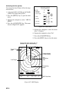
[ Installation Setup ]
Select item by omnipad
and ress ENTER key.
Auto Adjustment
Adjustment
Figure 6-21 Installation setup menu
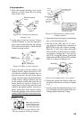
Adjusting tune/video
Do the following to adjust tune and video am-
plifier level input.
1. Press the [ST BY/TX] key to transmit.
WARNING
Before transmitting the radar make sure
no one is near the antenna unit, to pre-
vent the potential risk of being struck
by the rotating antenna and exposure
to RF radiation hazard.
2. On the Installation setup menu, select “8.
Tune/Video Adjustment” and press the
[ACQ/ENTER] key.
3. The unit automatically adjusts, displaying
the following message.
[ Tune/Video Auto Adjustment ]
Now under correction.
Return to illustration setup.
menu after the correction.
Figure 6-22 Tune/Video Auto
Adjustment messages
4. When adjustment is completed, the mes-
sages disappears.
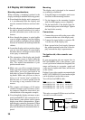
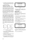
Entering antenna height
The STC curve changes with respect to an-
tenna height above the waterline. Enter an-
tenna height above the waterline to optimize
the STC curve.
1. Select “12. Antenna Height” on the instal-
lation setup menu and press the [ACQ/EN-
TER] key.
2. Operate the omnipad to select antenna
height above the waterline; Low (~3 m),
Mid (3~6 m) or High (6~10 m).
3. Press the [ACQ/ENTER] key.
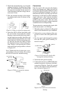
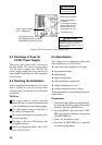
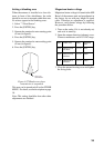
Aligning heading
(Adjustment sector:0~359.90)
You have mounted the antenna unit facing
straight ahead in the direction of the bow.
Therefore, a small but conspicuous target dead
ahead visually should appear on the heading
line (zero degrees).
In practice, you will probably observe some
small error on the display because of the dif-
ficulty in achieving accurate initial position-
ing of the antenna unit. The following
adjustment will compensate for this error.
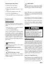
1. Identify a suitable target (for example, ship
or buoy) at a range between 0.125 to 0.25
nautical miles, preferably near the head-
ing mark. To lessen error, keep echoes in
the outer half of the picture by changing
the range. Also, be sure the zoom and off
center functions are off.
2. Select “9. Heading Alignment” on the in-
stallation setup menu and press the [ACQ/
ENTER] key. The following message ap-
pears on the display.
[ Heading alignment ]
Set EBL1 to center of target
dead ahead and press ENTER.
Correction 0.0°
<Press MENU for inst setup>
Figure 6-23 Heading alignment message
3. Operate the omnipad to bisect target se-
lected at step 1 with the heading line.
4. Press the [ACQ/ENTER] key.