


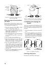
10
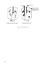
VRM1
Offset EBL
(EBL1)
6.0 NM
2.0
EBL1 origin
(initial position
of target)
Target moved
here.
EBL1
bearing
70.0° R
VRM
6.0 NM
VRM1
range
EBL
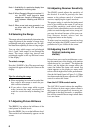
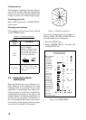
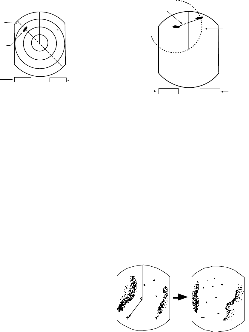
Figure 2-10 Predicting collision course by
using the offset EBL
Measuring range and bearing between
two targets
The procedure which follows shows how to
measure the range and bearing between target
“A” and target “B” in Figure 2-11.
1. Press the omnipad to place EBL1’s origin
(cursor) on the center of target “A”.
2. Press the [EBL/VRM SELECT] key to
choose EBL1 readout and then press the
[EBL/VRM CONTROL] key.
3. Select EBL OFFSET on the menu and press
the [ACQ/ENTER] key. EBL1’s origin shifts
to cursor.
4. Press the [EBL/VRM CONTROL] key.
5. Press the omnipad to bisect target “B” with
EBL1. Check the EBL1 readout to find the
bearing between target “A” and target “B”.
6. Press the [EBL/VRM SELECT] key to
choose VRM1 readout. Press the omnipad
to place the outside edge of VRM1 on the
inside edge of target “B.” Check the VRM1
readout to find the range between target “A”
and target “B”.
7. To cancel, select EBL OFFSET on the menu
and press the [ACQ/ENTER] key.
VRM1
EBL1
bearing
70.0° R
VRM
4.5 NM
VRM1
range
EBL1
A
B
Figure 2-11 Measuring the range and bearing
between two targets by using the offset EBL
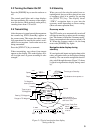
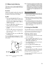
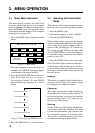
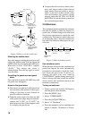
2.15 Shifting (off centering) the
Picture
Your vessel’s position can be shifted up to 75%
of the range in use to view the situation around
your vessel without changing the range or size
of targets.
1. Press the omnipad to set cursor where de-
sired.
2. Press the [F1 (A/C SEA)] control if its func-
tion is set for SHIFT (default setting), or se-
lect SHIFT on the menu. OFFCENTER
appears at the top right corner of the display
when the picture is shifted.
Cursor Cursor
1 Place cursor
where desired.
2 Press SHIFT ZOOM
key to off center display.
Figure 2-12 Shifting the picture
Cancelling shifted picture
Press the [F1 (A/C SEA)] control again.