


26
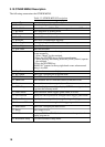
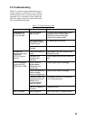
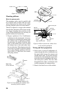
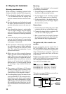
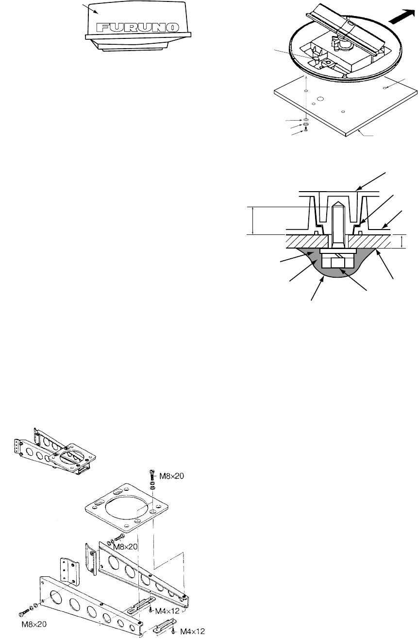
Radome cover
Figure 6-2 Antenna unit
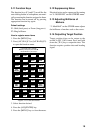
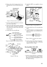
Mounting platform
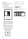
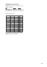
Holes for antenna unit:
The mounting surface must be parallel with
the waterline and provided with five holes
whose dimensions are shown in the outline
drawing attached at the end of this manual.
The unit is adjusted so a target echo returned
from the bow direction will be shown on the
zero degree (heading line) position on the
screen. When drilling holes, be sure they are
parallel with the fore and aft line.
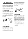
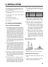
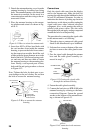
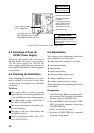
3. Prepare a platform of 5 to 10 millimeters
in thickness for the antenna unit. (A mount-
ing bracket for mounting the antenna unit
on a sailboat mast is optionally available.
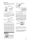
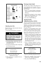
See the below for details.) Find the cable
entry on the radome base. Next, position
the radome base so the cable entry faces
the stern direction. This alignment must be
as accurate as possible. Fasten the radome
base to the mounting platform with four
each of M10 x 25 hex bolts, flat washers
and spring washers.
Type: OP03-92
Code no.: 008-445-070
Figure 6-3 Assembling the sailboat mast
mounting bracket (option)
Mask size;
φ70 to φ125 mm
SHIP'S BOW
CABLE
ENTRY
4-Ø12 HOLES
PLATFORM
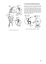
FLAT WASHER
SPRING WASHER
M10 X 25 HEX BOLT
Flat
washer
Spring
washer
Platform
Antenna base plate
M10 x 25
Hex bolt
Radome
5 - 10 mm
Apply silicone sealant
Effective
thread length
25 mm
Packing
Figure 6-4 How to fasten the radome base
to the mounting platform
Wiring and final preparation
4. Drill a hole of at least 20 millimeters di-
ameter through the deck or bulkhead to run
the signal cable between the antenna unit
and the display unit. (To prevent electrical
interference avoid running the signal cable
near other electrical equipment and in par-
allel with power cables.) Pass the cable
through the hole. Then, seal the hole with
sealing compound for waterproofing.
5. Remove the shield cover in the radome.