


30
6.2 Display Unit Installation
Mounting considerations
When selecting a mounting location for the
display unit keep in mind the following points.
¡ Even though the display unit is waterproof,
it is recommended that the display unit
must be mounted inside an enclosed cabi-
net.
¡ Provide adequate space behind and around
the unit to permit circulation of air and to
provide convenient access to the rear con-
nectors.
¡ Even though the picture is quite legible
even in bright sunlight, keep the display
unit out of direct sunlight or at least shaded
because of heat that can build up inside the
cabinet.
¡ Locate the display unit in a position where
you can view and operate it conveniently
but where there is no danger of salt or fresh
water spray or immersion.
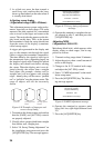
¡ The orientation of the display unit should
be so the radar screen is viewed while the
operator is facing in the direction of the
bow. This makes determination of your
position much easier.
¡ Make sure you allow enough clearance
both to get to the connectors behind the unit
and to allow you to get your hands in on
both sides to loosen or tighten the mount-
ing knobs. Make sure you leave at least a
foot or so of “service loop” of cables be-
hind the unit so it can be pulled forward
for servicing or easy removal of the con-
nectors.
¡ The compass safe distance of 0.8 meters
(standard compass) and 0.6 meters (steer-
ing compass) should be observed to pre-
vent deviation of the magnetic compass.
¡ Even though the display unit meets water-
proof standard IPX-5, the connection of ex-
ternal buzzer, radar plotter and/or remote
display can affect waterproofness. Water-
tight integrity cannot be guaranteed. When
these modification has been done, the dis-
play unit should not be mounted where ex-
posed.
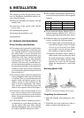
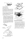
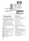
Mounting
The display unit is designed to be mounted
on a tabletop or bulkhead.
1. Using the hangar as a template, mark screw
locations in the mounting location.
2. Fix the hanger to the mounting location
with five M6 tapping screws (supplied).
3. Fit the knob bolts to the display unit. In-
stall the display unit in the hunger. Tighten
the knob bolts securely.
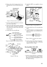
Connections
1. Connect the power cable to the power cable
connector on the rear of the display unit.
2. Connect the signal cable to connector DJ-
1 on the rear of the display unit.
3. Run a ground wire (local supply) between
the ground terminal on the rear of the dis-
play unit and the ship’s superstructure.
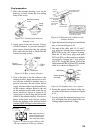
Navigation aid, video sounder con-
nection
If your navigation aid can output data in
IEC1162(NMEA 0183) data format, your
vessel's position in latitude and longitude, the
range and bearing to waypoint, speed and
course may be input to this radar, and be seen
on the screen.
Further if your video sounder can output depth
in IEC1162 (NMEA 0183) data format, depth
can be displayed on the radar screen.
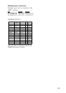
You will need an NMEA cable:
Type Code no. Remarks
MJ-A6SPF0012-050 000-134-424 6P-6P (5m)
MJ-A6SPF0012-100 000-133-817 6P-6P (10m)
MJ-A6SPF0003-050 000-117-603 w/connector
MJ-A6SPF0009-100 000-125-236 w/connector
This radar can output NAV data received from
a navaid to an echosounder.
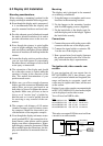
1832/1932/1942
SPU9211
J1352 (NMEA)
J1354
Navaid
Echo-
sounder
INT9213
(TLL)