


35
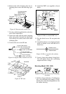
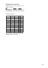
Magnetron heater voltage
Magnetron heater voltage is formed at the MD
Board of the antenna unit and preadjusted at
the factory for use with any length of signal
cable. Therefore no adjustment is required.
However, verify heater voltage by following
the procedure below.
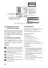
1. Turn on the radar (if it is not already on)
and set it in stand-by.
2. Open the antenna housing (radome) cover.
Connect a multitester, set to 10 V DC range.
3. Close the antenna housing cover and tighten
the fixing bolts.
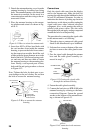
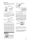
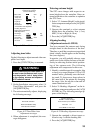
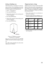
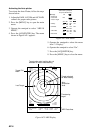
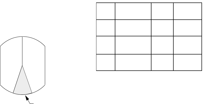
Setting a blanking area
When the antenna is installed at a close dis-
tance in front of the wheelhouse, the radar
should be set not to transmit within that area.
No echoes appear in the blanking areas.
1. Select "7. Dead Sector".
2. Press the [ENTER] key.
3. Operate the omnipad to enter starting point
of area (in figures).
4. Press the [ENTER] key.
5. Operate the omnipad to enter ending point
of area (in figures).
6. Press the [ENTER] key.
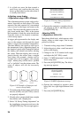
Area of no
transmission
Figure 6-27 Blank areas where
transmission is suspended
This area can be turned on/off on the OTHER
MENU. For detail, see the description on page
18.
Note: This setting should be done after other
adjustments are finished.
Model Check Point Rating Adjustment
point
M1832 TP802 #4, #6 on
PTU Board
7.4~7.6V R106
M1932 TP803 #4, #6 on
MD Board
7.4~7.6V VR801
M1942 TP803 #4, #6 on
MD Board
7.5~7.7V VR801