


28
Connections
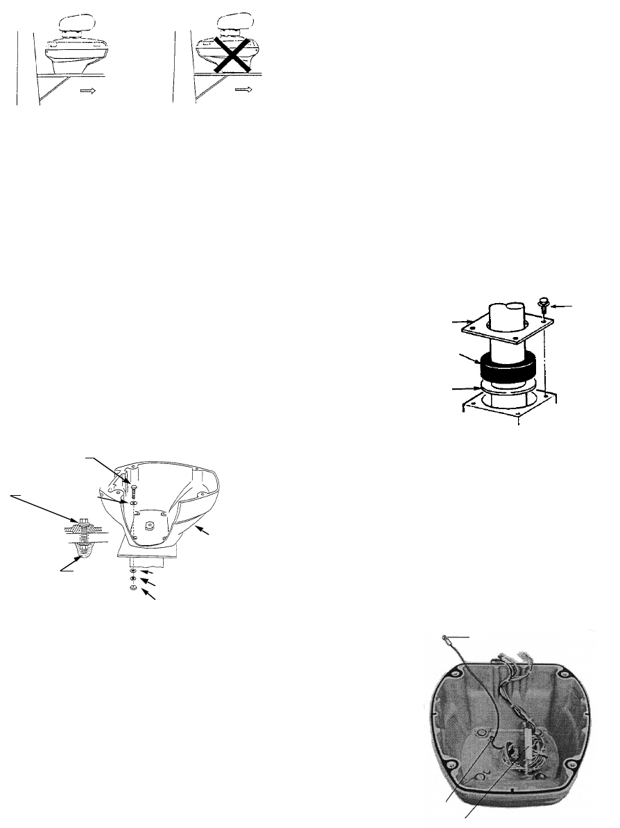
Only the signal cable runs from the display
unit to the antenna unit. Make the hole for
passing the cable through the bulkhead or deck
at least 20 millimeters diameter. In order to
minimize the chance of picking up electrical
interference, avoid where possible routing the
signal cable near other onboard electrical
equipment. Also, avoid running the cable in
parallel with power cables. Pass the cable
through the hole and apply sealing compound
around the hole for waterproofing.
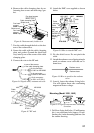
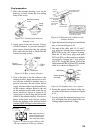
The procedure for connecting the signal cable
to the antenna unit is as following.
1. Through a pipe or waterproof cable grand
fitted on the wheelhouse top or bulkhead.
2. Unfasten four screws at bottom of the scan-
ner base to remove the cable gland assem-
bly.
3. Pass the signal cable through the antenna
base and the cable gland assembly (re-
moved in step 2.)
4-M4x10
CLAMP PLATE
PACKING
FLAT
WASHER
Figure 6-13 Passing the signal cable
through the antenna housing
4. Fasten the cable gland assembly.
5. Connect the lead wires to RTB-9100 in the
antenna housing by referring to the Inter-
connection Diagram. Fasten the ground
washer at the bottom of the antenna hous-
ing as shown in Figure 6-13.
GROUND WIRE
Fasten
shield here.
RTB-9100
Figure 6-14 Connection in the antenna
housing
2. Detach the antenna housing cover from the
antenna housing by loosening four fixing
bolts. The antenna housing cover fitted with
the transceiver module can be stored in a
convenient place until the wiring to the an-
tenna unit is done.
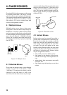
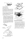
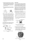
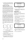
3. Place the antenna housing on the mount-
ing platform and orient it as shown in Fig-
ure 6-11.
Ship's
bow
Ship's
bow
Figure 6-11 How to orient the antenna unit
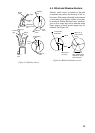
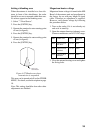
4. Insert four M12 x 60 hex head bolts with
the seal washers from inside the antenna
housing, to prevent the bolts from contact-
ing the transceiver module. Install the seal
washer with the larger diameter next to the
head of the bolt. Coat flat and spring wash-
ers and nuts and then use them to fasten
the antenna housing to the mounting plat-
form. Finally, coat exposed parts of nuts,
bolts and flat and spring washers as shown
in Figure 6-12.
Note: Tighten the bolts by their nuts to pre-
vent damage to the seal washer. Do not turn
the bolts to secure the antenna housing.
Hex head bolt
(M12 x 60)
Seal washer
Silicone
sealant
Flat washer
Spring washer
Hex head nut
Scanner
housing
Figure 6-12 How to mount the antenna
housing