


307-01-16 307-01-16Automatic Transaxle/Transmission
ASSEMBLY (Continued)
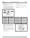
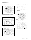
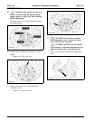
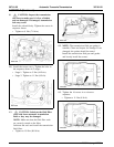
74. NOTE: Align the disc holes on special tool
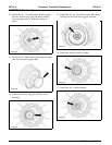
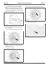
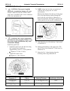
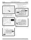
72. CAUTION: If the strut is installed
with the slot in gauge bar for correct
incorrectly, transmission damage will occur.
measurement.
Check to make sure that the overdrive band
Measure the distance from the top of the gauge
apply strut is installed in the correct orientation
bar to the drum bearing surface through the
to the case and piston rod.
hole in the disc and record as dimension A.
Repeat measurement 180 degrees opposite side
of the special tool and record as dimension B.
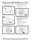
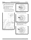
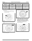
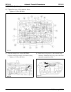
73. CAUTION: The torque specifications
are critical for this procedure. Failure to use
the correct torque specifications may cause
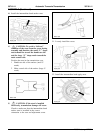
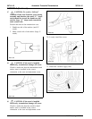
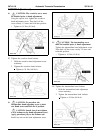
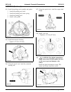
75. Add dimension A to B, divide by 2 and record
transmission damage.
as dimension C.
Install the special tool.
76. Subtract the thickness of the gauge bar 17.78
1 Install the special tool and the bolts using
mm (0.70 in) from dimension C, and record as
the 2 pump screw locations at
dimension D.
approximately 6 and 12 o’clock positions.
X Tighten to 15 Nm (11 lb-ft).
77. Select the No. 1 thrust bearing from the
2 Tighten the center screw.
following chart using dimension D.
X Tighten to 1 Nm (10 lb-in).
Service Part Number
Dimension D (7D014) Bearing Thickness Identification (Color/ID)
38.05-38.13 mm F7TZ-TA 1.55-1.60 mm (0.061-0.063 White
(1.50 in) in)
38.14-38.28 mm F7TZ-MA 1.75-1.80 mm (0.069-0.071 Green
(1.50-1.51 in) in)
2005 Mustang, 12/2004