


important that the following precautions are
observed.
3 Never start the engine if the battery leads
are loose.
4 Do not stop the engine by pulling off a
battery lead.
5 Remove the control unit if ambient
temperature (paint drying oven) is above 80ºC
(176ºF).
6 Never connect or disconnect the multi-plug
at the control unit unless the ignition is
switched off.
7 Disconnect the battery negative lead before
carrying out electric body welding.
10 Digiplex (electronic) ignition
- checks and adjustments
3
1 Without special equipment, any work on the
system components should be restricted to
the following.
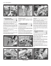
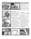
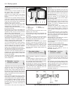
Engine speed sensor
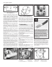
2 The gap between the sensor and the teeth
of the flywheel should be between 0.25 and
1.3 mm (0.0099 to 0.0512 in). Any
deviation will be due to mechanical damage to
the sensor, no adjustment being possible.
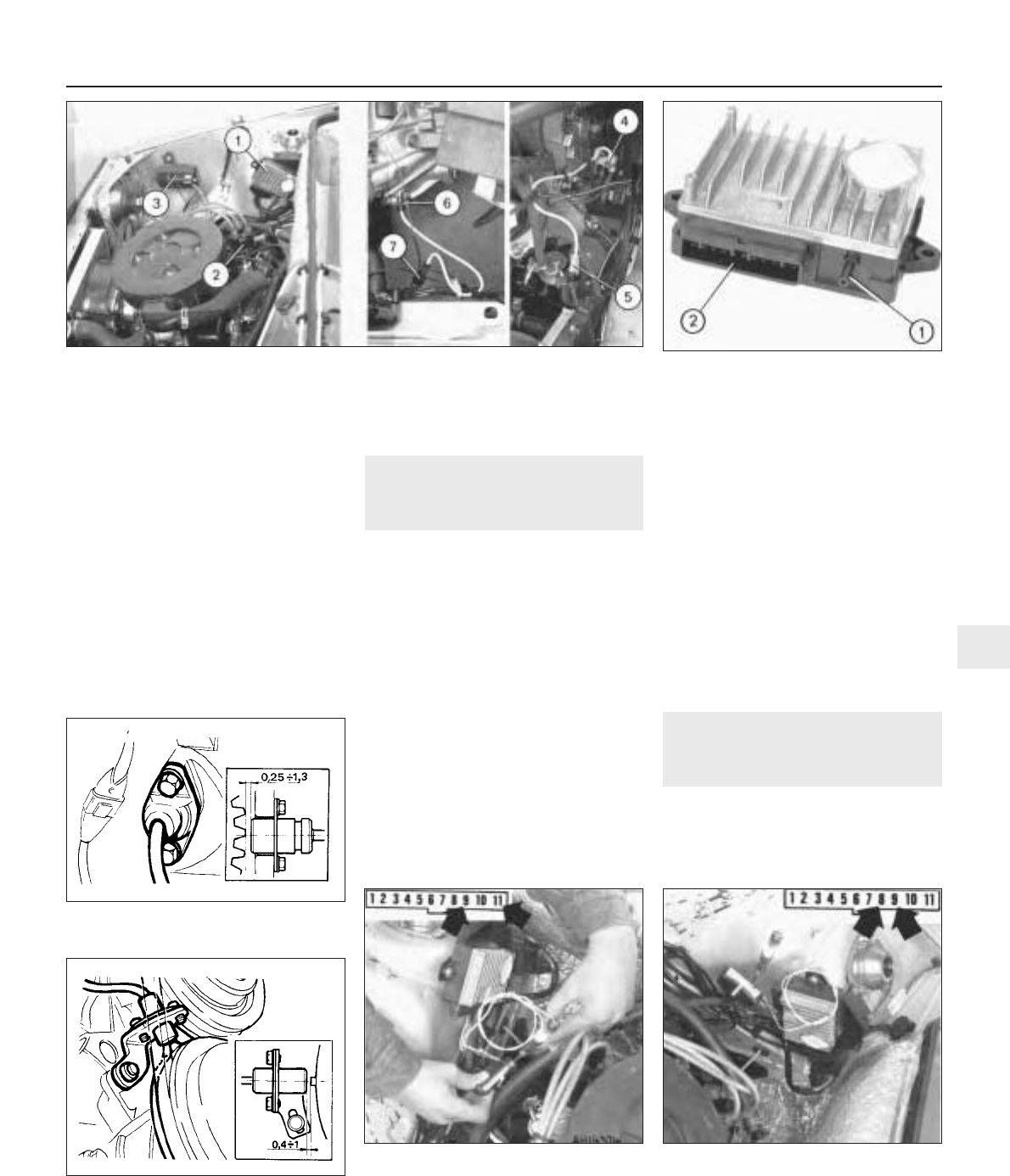
TDC sensor
3 The gap between the sensor and one of the
TDC reference marks on the crankshaft pulley
should be between 0.4 and 1.0 mm (0.016 to
0.039 in).
4 Any deviation will be due to the sensor
plate becoming loose. To reposition it will
necessitate setting No. 1 piston at TDC which
can only be carried out accurately by your
dealer using special tools.
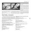
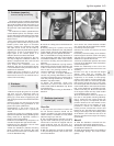
Supply circuit and continuity of
coil primary winding
5 Connect a test lamp between contacts 11
and 9 of the multi-plug having first pulled it
from the control unit.
6 Switch on the ignition, the test lamp should
come on. If it does not, either the connection
at the positive pole of the control unit or the
coil primary winding is open.
Control unit earth
7 Connect a test lamp between contacts 8
and 9 of the multi-plug having first pulled it
from the control unit. Switch on the ignition,
the test lamp should come on. If it does not,
improve the earth connection.
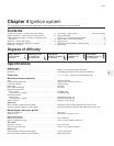
11 Spark plugs
1
1 The correct functioning of the spark plugs is
vital for the correct running and efficiency of the
engine. It is essential that the plugs fitted are
appropriate for the engine, and the suitable type
is specified at the beginning of this chapter. If
Ignition system 4•7
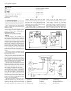
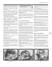
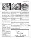
Fig. 4.9 Digiplex control unit (Sec 9)
1 Vacuum hose connector
2 Multi-plug socket
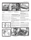
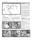
1 Control unit
2 Distributor
3 Ignition coil
4 TDC sensor
5 Wiring connector plug
6 Engine speed sensor
7 Wiring connector plug
Fig. 4.8 Location of Digiplex ignition system components (Sec 9)
Fig. 4.13 Test lamp connected between
terminals 8 and 9 of control unit multi-plug
(Sec 10)
Fig. 4.12 Test lamp connected between
terminals 11 and 9 of control unit
multi-plug (Sec 10)Fig. 4.11 TDC sensor gap (Sec 10)
Fig. 4.10 Engine speed sensor gap
(Sec 10)
4