


adjustments described in this sub-Section,
however, will require removal of the
carburettor.
39 Disconnect the short, curved diaphragm
hose from the top cover.
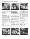
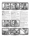
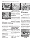
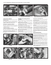
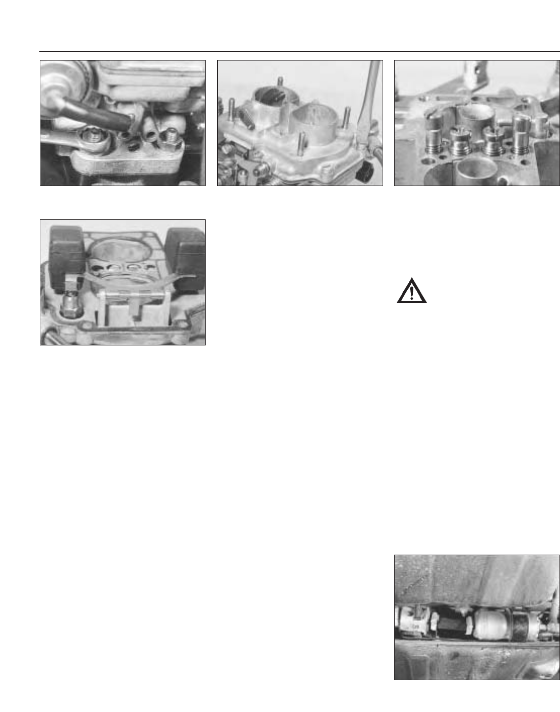
40 Extract the top cover screws, lift the cover
from the carburettor body, and rotate it in
order to release the cranked choke control
rod from its key hole (photo). Mop out the fuel
and clean the jets.
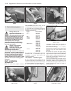
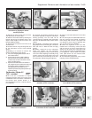
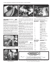
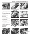
41 Check the jet sizes and other components
against those listed in the Specifications, in
case a previous owner has substituted
incorrect components (photo).
42 Overhaul procedures are generally as
given in Chapter 3, Section 14 for the Weber
30/32 DMTR, but use the Specifications listed
in this Chapter. Additional overhaul
procedures are given here.
Fuel inlet needle valve
43 If a high float level causing flooding of the
carburettor has been evident, first check that
the inlet valve housing is tight, and its washer
is sealing satisfactorily. A leak here will cause
fuel to bypass the inlet valve.
44 If the needle valve is to be renewed,
remove it in the following way.
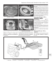
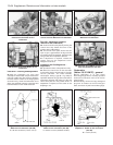
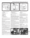
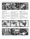
45 Access to the fuel inlet needle valve is
obtained by carefully tapping out the float arm
pivot pin. Take care, the pivot pin pillars are
very brittle (photo).
46 Unscrew the fuel inlet valve body and
remove the valve and washer.
47 When refitting the new valve, always use a
new sealing washer.
Float stroke (travel) - see Fig. 3.10
48 The float stroke should be between 42.5
and 43.5 mm when measured from the top
cover gasket. Adjust if necessary by bending
the tab on the end of the arm.
Accelerator pump
49 Adjustment of the accelerator pump is
very rarely required, but if performance is
suspect, carry out the following operations.
50 Fill the carburettor float chamber and then
operate the throttle valve plate lever several
times to prime the pump.
51 Position a test tube under the accelerator
pump jet and give ten full strokes of the
throttle lever, pausing between each stroke to
allow fuel to finish dripping.
52 The total volume of fuel collected should
be as specified. Adjust the nut on the pump
control if necessary to increase or decrease
the volume of fuel ejected.
General
53 When the stage is reached where the
valve plate spindle bushes have worn, then
the carburettor should be renewed complete.
54 When reassembling the carburettor, use
new gaskets which can be obtained in a repair
pack.
Carburettor (Weber 32 ICEV
61/250 and DMTE 30/32,
DMTE 30/150) - general
55 These carburettor types are fitted to later
models according to engine type. They are
similar in structure and operation to their
equivalents described in Chapter 3. Reference
can therefore be made to that Chapter for the
description and any operations concerning
them, but refer to Section 2 of this Chapter for
their specifications.
Carburettor (Solex
C 30/32-CIC 8) - description
56 This carburettor is fitted as an alternative
to the Weber unit on 1116 cc models
produced for certain markets. The removal,
refitting and overhaul procedures are
essentially the same as described earlier for
the Weber carburettors.
PART C:
BOSCH LE2-JETRONIC
FUEL INJECTION SYSTEM
Description
Warning: Refer to the beginning
of this Section before starting
any work.
1 The Bosch LE2-Jetronic fuel injection
system, fitted to the 1301 cc Turbo ie model,
is an electronically controlled multi-point
injection (MPi) system.
2 The fuel injectors are fed at constant
pressure in relation to inlet manifold vacuum
pressure.
3 The system electronic control unit (ECU)
actuates the injectors for variable duration,
and so supplies the precise volume of fuel
required for any given engine speed and load
condition.
4 The ECU also monitors the air induction, air
temperature, coolant temperature and throttle
opening as additional parameters to compute
the required opening of the fuel injectors,
giving maximum power with fuel economy.
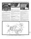
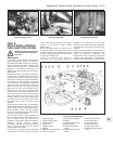
Fuel supply system
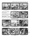
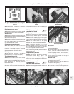
5 The fuel supply system consists of an
electric pump and primary filter, located
adjacent to the fuel tank. A fuel pressure peak
damper is located next to the pump (photo).
6 Fuel is then pumped through a filter to the
fuel rail and injectors. The injectors are of the
13•66 Supplement: Revisions and information on later models
9C.5 Electric fuel pump/filter/pressure
damper assembly location on a 1301 cc
Turbo ie model
9B.41 Jets on the Weber 30/32 DMTE
carburettor (top cover removed)
9B.45 Float pivot arrangement and needle
valve on the Weber 30/32 DMTE
carburettor
9B.40 Unscrewing a top cover screw from
the Weber 30/32 DMTE carburettor
9B.37F Unscrewing a carburettor fixing nut