


TDC sensor
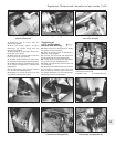
48 Insert the probes of the ohmmeter
between terminals 1 and 2 of the multipin
connector; 618 to 748 ohms (1301 cc) or 578
to 782 ohms (1372 cc) should be indicated.
49 If necessary, carry out a check of the gap
between the sensor and the crankshaft pulley,
as described in Chapter 4, Section 10.
ECU supply
50 Switch on the ignition, and then insert the
probes of a voltmeter between terminals 13
and 11 of the multipin connector. Battery
voltage should be indicated. If not, check the
battery earth, ignition switch or intermediate
connector plug for security.
Power module supply (1301 cc)
51 Pull the multipin plug from the power
module, and connect the probes of a
voltmeter between terminal 4 of the connector
and earth. If the reading is less than battery
voltage, check the security of all connections
between the ignition switch and terminal + 15
of the ignition coil.
52 Reconnect the multipin connector to the
ECU, but have the one from the power
module disconnected, and then switch on the
ignition.
53 Connect the voltmeter between terminals
4 and 2 of the power module multipin
connector. If the indicated voltage is less than
battery voltage, check the security of all
connections between the ignition switch and
terminal + 15 of the ignition coil, and the
battery earth. If all are satisfactory, check for
continuity between terminals 11 and 12. If
continuity is broken, renew the ECU.
Power module (1372 cc)
54 Proceed as described in paragraph 53.
Anti-knock sensor
55 If “pinking” occurs, or loss of power is
noticed, test the sensor by substitution of a
new one.
Ignition coil
56 Disconnect the leads from terminals 1
and 15 on the coil before testing.
57 Using the ohmmeter, check the resistance
of the primary winding. This should be
between 0.31 and 0.37 ohms (1301 cc) or
0.40 to 0.49 ohms (1372 cc), at an ambient
temperature of 20ºC (68ºF).
58 The secondary winding resistance should
be between 3330 and 4070 ohms (1301 cc) or
4320 to 5280 ohms (1372 cc), at an ambient
temperature of 20ºC (68ºF).
Distributor
59 Check the resistance of the rotor arm,
which should be between 800 and
1200 ohms.
60 Where all the foregoing tests have proved
satisfactory, then any problem must be due to
a fault in either the power module or the ECU.
These components can only be checked by
the substitution of a new unit - power module
first, then the ECU.
Safety pressure switch
61 The device protects the engine from
excessive turbocharging pressure, cutting off
the ignition by earthing the Microplex ECU.
Testing is not possible without a special
pressure pump, so the easiest way to check a
suspected fault is to fit a new unit.
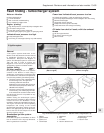
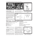
Digiplex 2 ignition system -
description
62 This system operates in a similar manner
to that of the earlier type described in Chap-
ter 4, but the circuit layout differs to suit the
Mono Jetronic fuel injection system. In
operation, the main difference is that the
Digiplex 2 system has a greater number of
13•90 Supplement: Revisions and information on later models
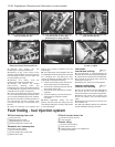
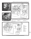
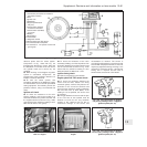
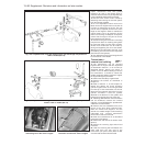
Fig. 13.81 Microplex ignition system
control unit connection (Sec 10)
For colour code, see main wiring diagrams
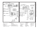
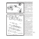
Fig. 13.80 Microplex ignition system ECU multipin connector (Sec 10)
For colour code, see main wiring diagrams
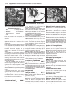
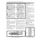
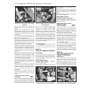
Fig. 13.79 Ignition advance curves - Microplex ignition system on the 1301 cc Turbo ie
(Sec 10)