mounted on the front end of the crankshaft
and driven by it.
11 The flexible toothed timing belt drives the
camshaft and the coolant pump from a
sprocket on the front end of the crankshaft.
The belt is tensioned by an
eccentrically-mounted pulley.
12 The distributor and the fuel pump
(carburettor models) are driven from the
flywheel end of the camshaft. The fuel pump
on fuel injection models is an integral unit
combined with the fuel gauge sender unit and
immersed in the fuel tank.
PART B:
OPERATIONS POSSIBLE
WITH ENGINE IN CAR
Valve clearances - adjustment
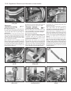
1 The operations are similar to those
described in Chapter 1, Section 26, but note
that the special tools referred to have different
part numbers for the FlRE engine -
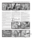
1860443000 and 1887001000 (photos).
2 Remember that the clearance for inlet and
exhaust valves differs see Specifications at
the beginning of this Supplement.
3 Counting from the timing cover end of the
engine, the valve sequence is as follows.
Inlet 2-4-5-7
Exhaust 1-3-6-8
Timing belt - renewal #
4 Remove the air cleaner.
5 Slacken and remove the alternator
drivebelt, then remove the spark plugs.
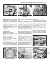
6 Unbolt and remove the timing belt cover.
Note the bolt located at the bottom of the
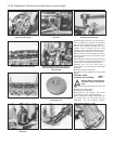
cover, this can be easily overlooked (photo).
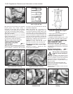
7 Unbolt and remove the crankshaft pulley
(photo).
13•20 Supplement: Revisions and information on later models
5B.7 Unscrewing the crankshaft pulley
bolts
5B.6 Timing cover lower fixing bolt
removal
5B.1B Using a modified C-spanner and
screwdriver to remove a shim
5B.1A Checking a valve clearance
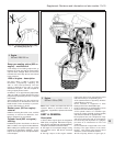
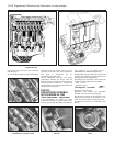
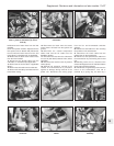
Fig. 13.3 Longitudinal sectional view of the 999 and 1108 cc
engine (Sec 5A)
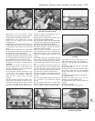
Fig. 13.4 999 and 1008 cc engine lubrication system (Sec 5A)


