


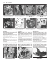
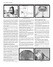
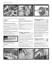
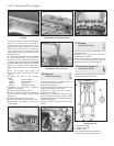

17 Screw in the camshaft front bearing
lockscrew (photo).
Oil pump
18 Refit the oil pump as described in Sec-
tion 10.
Timing chain and sprockets
19 Fit the timing chain and sprockets as
described in Section 6. Fit the Woodruff key
to the crankshaft nose.
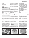
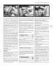
20 Using a new gasket, fit the timing chain
cover, but leave the bolts finger tight (photo).
21 Apply grease to the lips of the timing
cover oil seal and then push the crankshaft
pulley into position.
22 Move the timing cover if necessary so that
the pulley hub is centralised in the oil seal and
then tighten the cover bolts.
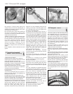
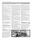
23 Screw on the crankshaft pulley nut and
tighten to the specified torque (photo).
Piston/connecting rods
24 Fit these as described in Section 9.
Sump pan
25 Fit the sump pan as described in Sec-
tion 8.
Cylinder head
26 Stand the engine upright and fit the
cylinder head as described in Section 7.
27 Insert the pushrods in their original fitted
order.
28 With the rocker arm adjuster screws fully
unscrewed, locate the rocker gear and screw
on the fixing nuts.
29 Adjust the valve clearances as described
in Section 5.
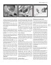
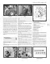
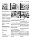
30 Locate a new gasket in position and fit the
rocker cover (photo).
31 Screw on a new oil filter (Section 2).
21 Engine - refitting ancillary
components
1 Refer to Chapter 5 and refit the clutch,
making sure to centralise the driven plate.
2 Fit the coolant pump as described in
Chapter 2. Fit the thermostat housing if it was
removed noting the air cleaner mounting
bracket on the housing studs.
3 Fit the alternator and drivebelt as described
in Chapter 9.
4 Refer to Chapter 3 and fit the exhaust
manifold and hot air collector, the carburettor
and spacer and the fuel pump.
5 Fit the distributor as described in Chapter
4. Fit the oil dipstick guide tube (photos).
22 Engine/transmission -
reconnection
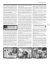
1
1 Support the weight of the transmission and
offer it squarely to the engine. The splined
input shaft should pass easily through the hub
of the driven plate, provided the plate has
been centralised as described in Chapter 5. It
may be necessary to align the splines with the
hub grooves, in which case have an assistant
turn the crankshaft pulley nut. The alignment
dowels will make the connection stiff, so
drawing the engine and transmission together
with two connecting bolts will ease it.
2 Once the engine and transmission are fully
engaged, insert and tighten all the connecting
bolts. Locate the lifting eyes.
3 Bolt on the flywheel housing cover plate
and the mounting brackets.
4 Bolt on the starter motor.
23 Engine/transmission -
refitting
3
1 The refitting operations are reversals of
those described in Section 13.
2 Observe the following special points.
3 Tighten the engine mounting and front
suspension (disconnected) bolts to the
specified torque when the hoist has been
1•22 903 cc engine
21.5B Dipstick guide tube support21.5A Dipstick guide tube20.30 Rocker cover nut and thrust plate
20.23 Tightening crankshaft pulley nut20.20 Timing cover20.17 Camshaft front bearing lockscrew
Hold the crankshaft against
rotation either by jamming
the starter ring gear or by
placing a block of wood
between a crankshaft web and the
inside of the crankcase.