


adjustment procedures are the same as those
outlined for the previous model units in
Chapter 9, but ensure that the load
compensation lever is turned to the “O”
(normal load setting) position before making
any adjustments.
Headlamp unit removal - later
models
32 The removal and refitting procedures
described in Chapter 9 also apply to the later
headlamp type, but note that later units are
secured in position by three retaining screws.
Headlamp dim-dip system -
description
33 On later models, the wiring circuit has
been modified to prevent the car being driven
on parking lamps only in built-up areas.
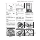
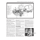
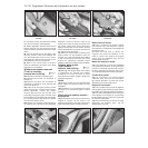
34 Headlamp intensity is reduced by the
transformer located at the front of the engine
compartment (photo).
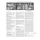
35 Any attempt to start the car with parking
lamps only on will automatically cause the
headlamps to switch on with a low-intensity
dipped beam. Dipped and main beam
function normally.
36 The headlamp dim-dip system is a legal
requirement for all UK models registered after
April 1st, 1987.
Front fog lamps - bulb/unit
removal and refitting
and beam adjustment ™
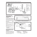
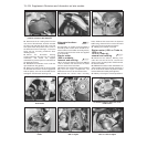
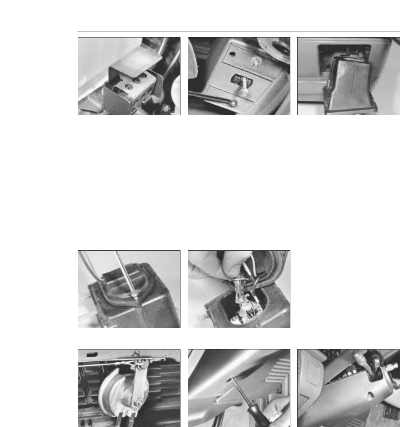
37 Ensure that the front fog lamps are
switched off, then unscrew the two retaining
screws and withdraw the lamp unit from the
underside of the front bumper (photos).
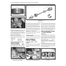
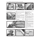
38 Undo the retaining screw and remove the
access cover from the unit (photo).
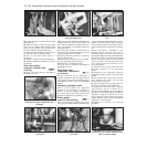
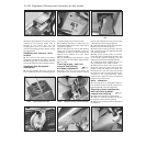
39 Disconnect the wiring connector from the
bulb, release the clips and withdraw the bulb
from the lamp (photo).
40 Refit in the reverse order of removal.
Check the light for satisfactory operation and
if the beam requires resetting, turn the
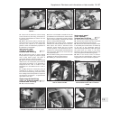
adjustment screw in the required direction.
41 To adjust the beam, position the car 5 m
from, and square on to, a wall or similar.
42 Measure the height of the centre of the
lamp lens from the ground and mark the
position on the wall. Switch on the lamp. The
demarcation line (cut-off) of the light should
be below the mark on the wall by 50 mm plus
one-third of the ground-to-lamp centre
measurement. Adjust the beam as required
using the long centre screw.
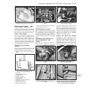
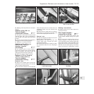
Horn - relocation
43 The single horn, on applicable models, is
now located behind the grille, bolted on a
bracket attached to the top rail (photo).
Steering column combination
switches (later models) -
removal and refitting
¡
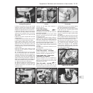
44 Disconnect the battery negative lead.
45 Undo the retaining screws and remove
the steering column shrouds (photos).
46 Remove the steering wheel as described
in Chapter 10.
13•106 Supplement: Revisions and information on later models
15.45B . . . then remove the upper . . .15.45A Undo the retaining screws . . .15.43 Horn location
15.39 . . . detach the wires, extract the bulb15.38 . . . remove the rear cover . . .
15.37B . . . and withdraw the front fog lamp
unit . . .
15.37A Undo the retaining bolts . . .15.34 Headlamp dim-dip transformer