


© 2006 Directed Electronics—all rights reserved 53
table of zones
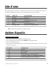
When using the Diagnostic functions, use the Table of Zones to see which input has triggered the system. It is
also helpful in deciding which input to use when connecting optional sensors and switches.
NOTE: The Warn Away® response does not report on the LED.
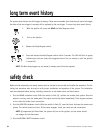
shutdown diagnostics
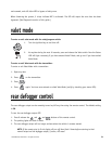
1. With the ignition OFF, press and HOLD the Valet/Program switch.
2. Turn the ignition ON and then back OFF while HOLDING the Valet/Program switch.
3. Release the Valet/Program switch.
4. Press and release the Valet/Program switch. The LED will report the last shutdown for one minute or until
the ignition is turned on.
LED FLASHES SHUTDOWN MODE
One Timed out
Two Over-rev shutdown
Three Low or no RPM
Four Transmitter shutdown (or optional push-button)
Six (-) Shutdown (H3/4 GRAY) or (+) Shutdown (H3/3 BROWN)
Seven (-) Neutral safety shutdown (H3/1 BLACK/WHITE)
Eight Wait-to-start timed out
to perform shutdown diagnostics
ZONE NO. TRIGGER TYPE INPUT DESCRIPTION
1 Trunk Input BLUE (H1/7)
2 Multiplexed Shock Sensor Input Mux BLUE wire.
3 Door Trigger GREEN (H1/8) and VIOLET (H1/6).
4 Multiplexed Shock Sensor Input Mux GREEN wire
5 Ignition Yellow ribbon harness wire
6 Hood Brake Trigger GRAY on the 6-pin shutdown harness.