


34 © 2006 Directed Electronics—all rights reserved
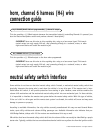
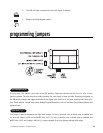
NOTE: For parking light circuits that draw 10 amps or more, the internal jumper must be switched
to a (-) light flash output. P/N 8617 or a standard automotive SPDT relay must be used on the
H1/11 light flash output harness wire.
transmitter/receiver learn routine
™
The system comes with one transmitter that have been taught to the receiver. The receiver can store up to 4 dif-
ferent transmitter codes in memory. Use the following learn routine to add transmitters to the system or to
change button assignments if desired.
The learn routine may be locked if previously programmed using the Bitwriter®. If the horn generates one long
honk when attempting to program the unit, the learn routine is locked and must be unlocked using the Bitwriter®
before proceeding.
The Valet/Program switch, plugged into the blue port, is used for programming. There is a basic sequence of steps
to remember whenever programming this unit: Door, Key, Choose, Transmit and Release.
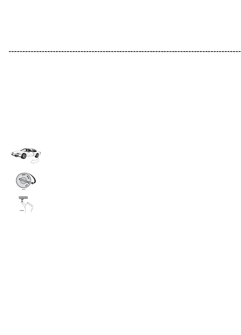
1. Open a door. (The GREEN wire, H1/8, or the VIOLET, H1/6 must be connected.)
2. Key. Turn the ignition to the ON position.
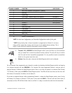
3. Choose. Within 10 seconds, press and release the Program switch the number of times cor-
responding to the desired channel listed below. Once you have selected the channel, press
the switch once more and HOLD it. The LED will flash and the horn will honk (if connected)
to confirm the selected channel. Do not release the Program switch.