


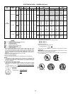


APPLICATION DATA
1. Units approved for outdoor installation only.
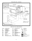
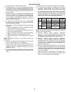
2. Ductwork (036-150) — Secure vertical discharge ductwork
to roof curb. For horizontal discharge applications, either at-
tach ductwork to unit, or use field-supplied flanges attached
to the horizontal discharge openings and attach all duct-
work to flanges.
3. Ductwork (180-300) — Ductwork should be attached to the
curb on all units. Interior installation may proceed before
unit is set in place on roof. If ductwork is to be attached to
unit, do not drill in condensate drain pan area — leaks may
result. Field-fabricated concentric ductwork may be con-
nected as shown on page 61.
4. On 180-300 size units with electric heat, a field-supplied
90° elbow must be installed in the supply ductwork below
the unit discharge connection.
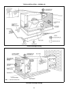
5. To convert from vertical discharge to horizontal discharge
(036-150):
a. Remove Durablade economizer or two-position damper
to gain access to return duct opening.
b. Move the horizontal-discharge duct opening covers to
the vertical discharge openings.
c. Rotate economizer or two-position damper 90 degrees.
d. Rotate the barometric relief damper 90 degrees.
e. Install block-off plate over the opening on the access
panel.
NOTE: Parablade economizer is only used for vertical dis-
charge units.
6. Roof curb connections allow field power wires and control
wires to enter through the roof curb opening.
7. Use of 2-stage heating and cooling thermostat is recom-
mended for all units. A 2-stage cooling thermostat is re-
quired on units with accessory economizer to provide
integrated cooling.
8. All units are automatic changeover from heating to cooling
when automatic changeover thermostat and subbase are
used.
9. Units are draw-thru on cooling and blow-thru on heating.
10. To minimize the possibility of condensate blow-off from
evaporator, airflow through units should not exceed
500 cfm/ton on 036-240 units and 11,250 cfm on 300 units.
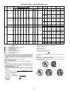
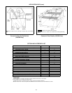
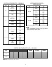
11. For cooling minimum airflow is 300 cfm/ton for 036-240
units and 280 cfm/ton on 300 units. For units with electric
heating, required minimum cfm is 900 for 036; 1200 for 048;
1500 for 060; 1800 for 072; 2250 for 090; 2550 for 102; and
3000 for 120 and 150, with the following exceptions:
UNIT
558D
UNIT
VOLTAGE
HEATER
kW
UNIT
CONFIGURATION
REQUIRED
MINIMUM
CFM
120,
150
208/230 42.4 Horizontal 3200
208/230 50.0 Horizontal 3200
460 50.0
Horizontal or
Vertical
3200
090-
150
575
18.0
Horizontal or
Vertical
2800
36.0 2350
NOTE: The 180-300 units with electric heating have a required
minimum heating of 300 cfm/ton.
12. Minimum ambient cooling operating temperature
(036-150) — The minimum temperature for size 036-150
standard units is 25 F. With accessory low-ambient kit, units
can operate at outdoor temperatures down to –20 F.
13. Minimum ambient cooling operation temperature
(180-300) — Units are designed to operate at outdoor tem-
peratures down to 40 F for 180, 35 F for 216, 25 F for 240,
and 48 F for 300. To operate at lower outdoor temperatures,
see Trade Prices or contact your local representative for
appropriate accessories.
14. Due to the internal unit design (draw-thru over the motor),
air path, and specially designed motors, the full horsepower
(maximum continuous bhp) listed in the Specifications table
and the notes following each Air Delivery table can be uti-
lized with confidence.
Using motors with the values listed in the Specifications
table
will not
result in nuisance tripping or premature motor
failure. The unit warranty will not be affected.
60